Radiator exit duct:
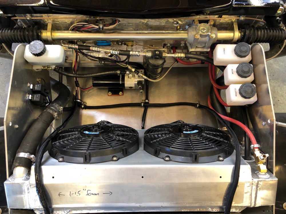
Before I could install my radiator exit duct (for good), I had to clean up the wiring in the radiator box. There’s a surprising amount of copper running back and forth through here!

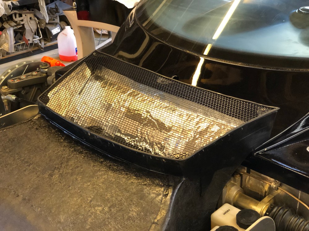
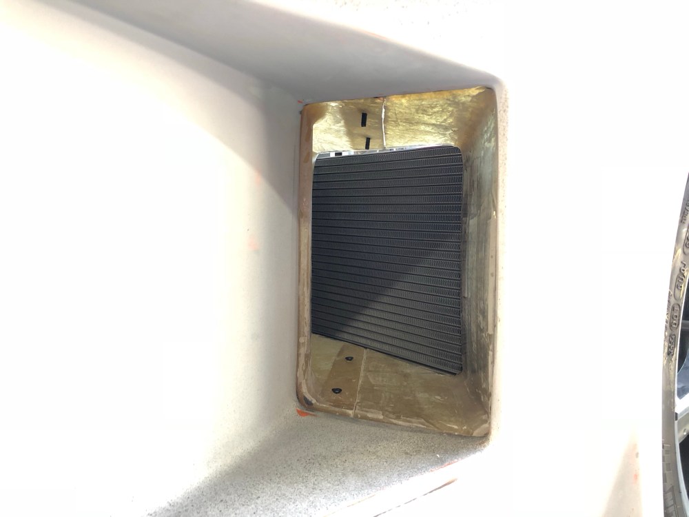
I used McMaster PN 92725T42 which is made from aluminum and has a 79% open area. I thought this would be enough so the exiting air wouldn’t be restricted due to the presence of the grill. The main purpose of the grill is to keep debris from falling into the box and collecting at the bottom (there’s a gap to allow water to drain but it’s not big enough for leaves).
I can’t say I’m a big fan of this material.
It’s relatively inexpensive but the very thin aluminum doesn’t have much strength – so it’s pretty easy to distort. McMaster PN 92725T22 has the exact same hole dimensions but is made from steel. It might have been smarter to go with this in lieu of the lighter aluminum. I’ll run this piece for a while and see how it holds up though it’s likely I’ll be looking for a different grill covering in the near future. The silver reflective material lining the duct is Second Skin Thermal Block; it’s actually a thin sheet of aluminum meant to deflect radiant heat. Other than the sun, the duct shouldn’t be getting much radiant heating so it’s not all that necessary. I’ll likely paint the interior black at some point in the future.
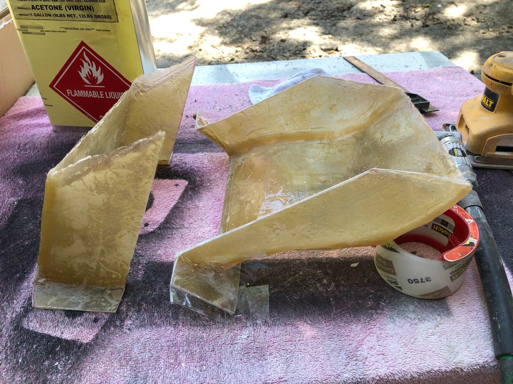
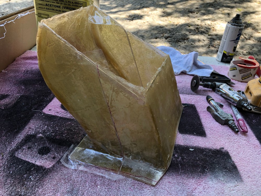
Oil cooler duct:
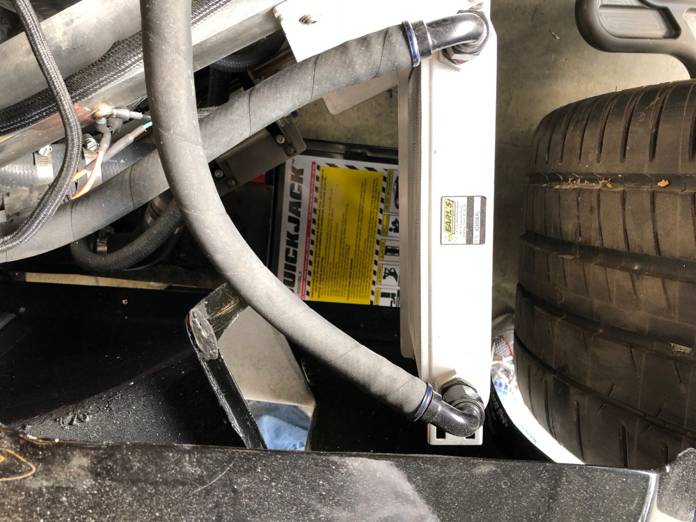
I needed to fabricate a similar duct for my oil cooler. The cooler is positioned just behind the driver side intake. Once air enters the interior bodywork it kind of just flows everywhere, it’s unlikely very much will actually flow THROUGH the oil cooler without some assistance.
When I initially positioned and mounted my oil cooler I had done so without the body in place. I took some rough measurements of the spider while it was on the ground and SWAG’d at some dimensions on the frame. When I eventually remounted my spider I discovered I had 2 issues:
- The oil cooler was not centered vertically with my revised intake opening.
- The oil cooler was positioned too far rearward and came dangerously close to the rear wheel.
Complicating things further on the re-do was my fuel system was set and I couldn’t move the oil cooler forward much because it would mean moving my fuel pumps!
Rock and a hard place.
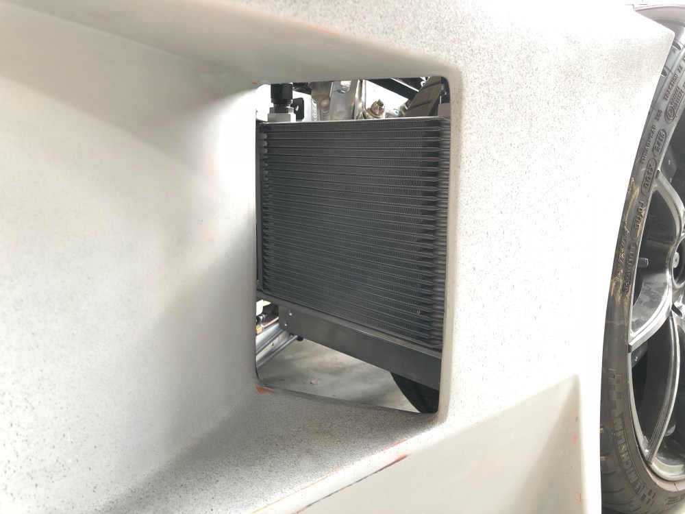
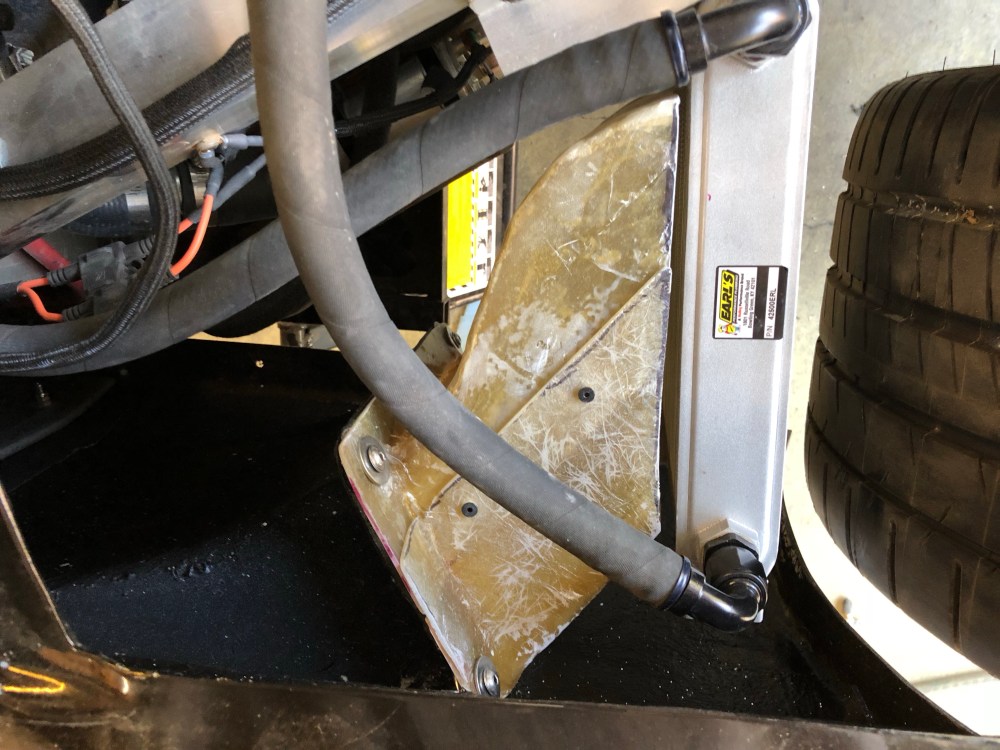
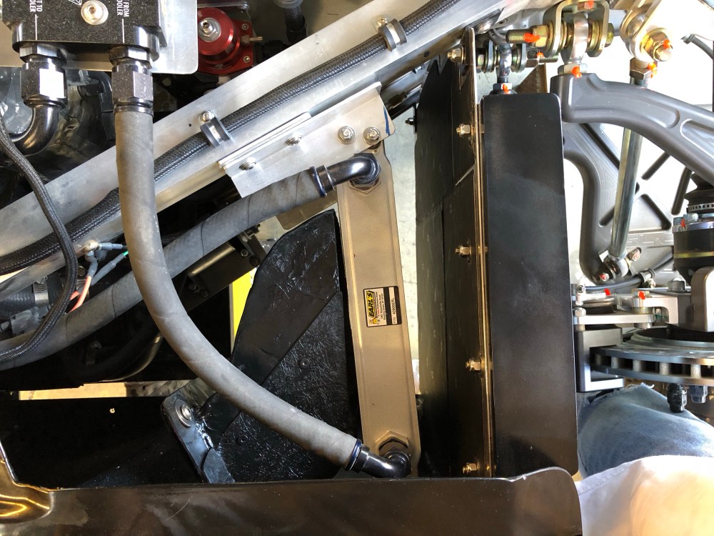
So I tweaked the oil cooler angle slightly and centered it vertically. Better, but not great. This also mucked with my oil cooler plumbing so that’s not ideal either … a few more items to the “future to-do list”.
The following photo shows it well; any air coming in this intake is going to flow above, below, and around the oil cooler instead of going through it – not so good for cooler efficiency!
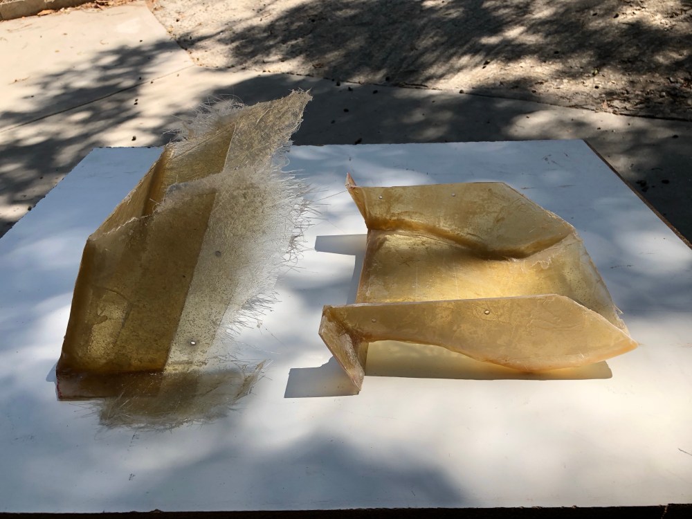
More fiberglass work …


The to-do list is shrinking!
