The roof mounted fresh air inlet for the engine bay needs a tunnel attached to the underside of the roof to create a sealed channel through which air can travel to the back of the car. Without a tunnel, air would just dump into the cavity above the ceiling panel and this would probably be pretty terrible for noise.
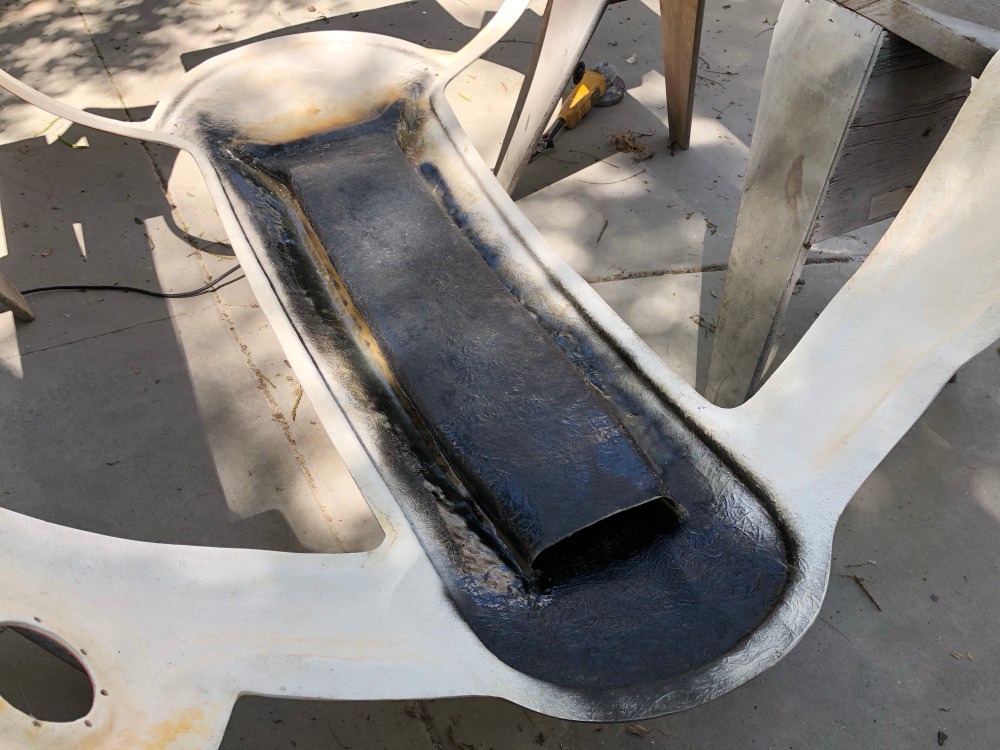
I purchased a fiberglass tunnel piece made by Jack (Molleur on the GT40s site). Knowing what I know now, I probably could have made this myself but Jack’s already got the tool and know-how to do this well – probably not much money saved by doing it myself. It’s about as large a tunnel as you can fit between the roll bars and still get things to fit reasonably well. I could fit 3 popsicle sticks on either side, wedged in between the tunnel and bars.
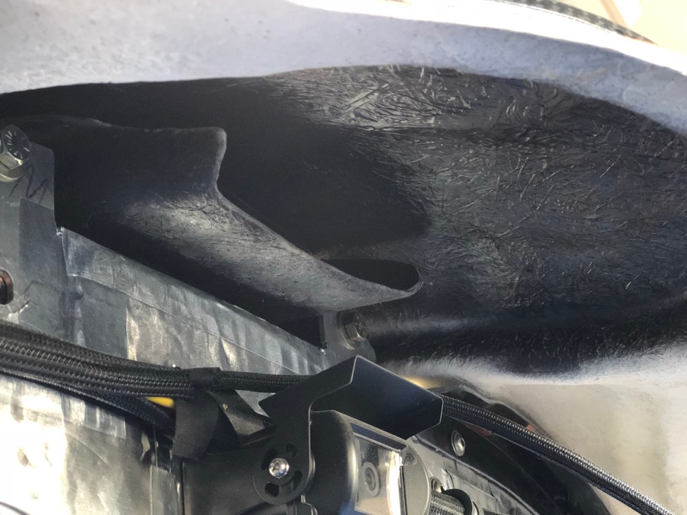
Before attaching the tunnel, I wanted to prep the interior just a touch. Once the tunnel is glassed onto the roof you won’t be able to get back in for additional work. The underside of the fiberglass body is white in color and is visible when looking in via the intake opening so I spray painted the underside of the roof in black semi-gloss. After the paint dried I then applied a layer of Damplifier to help knock down any vibrations caused by wind running along the surface of the roof.

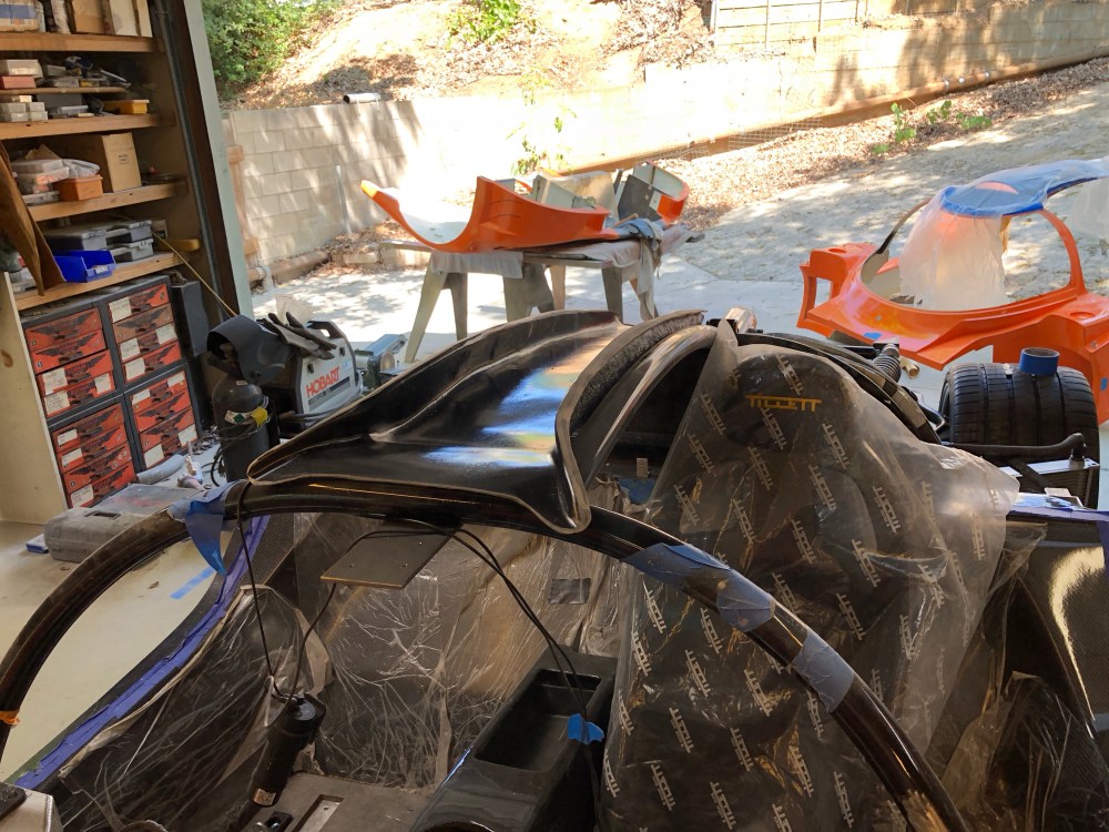
As I mentioned before, you want to be pretty darn sure the spider is properly aligned before glassing in the tunnel. I installed bolts into all the body fastening locations and set the doors on the body to make sure it was properly positioned side to side and that the curvature of the roof matched well to the doors – be sure to temporarily install whatever weatherstripping you plan on using at this time so the fit’s as close to final as you can get it. I then used popsicle sticks and wedges to temporarily hold the tunnel in place and did a final check that the roof was properly positioned.
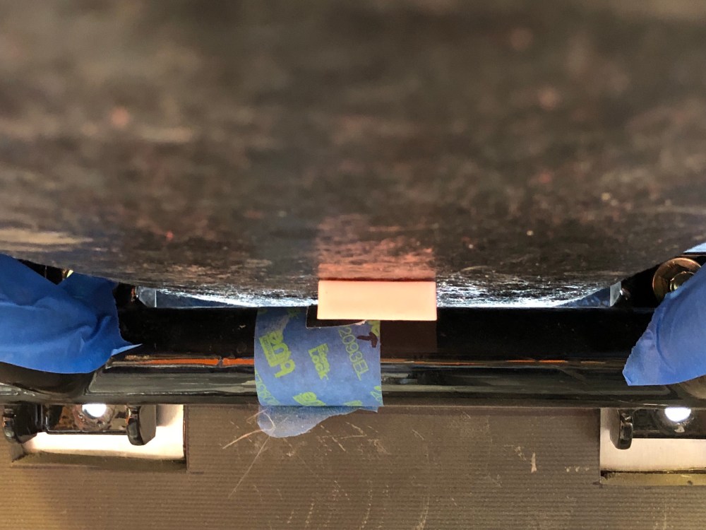
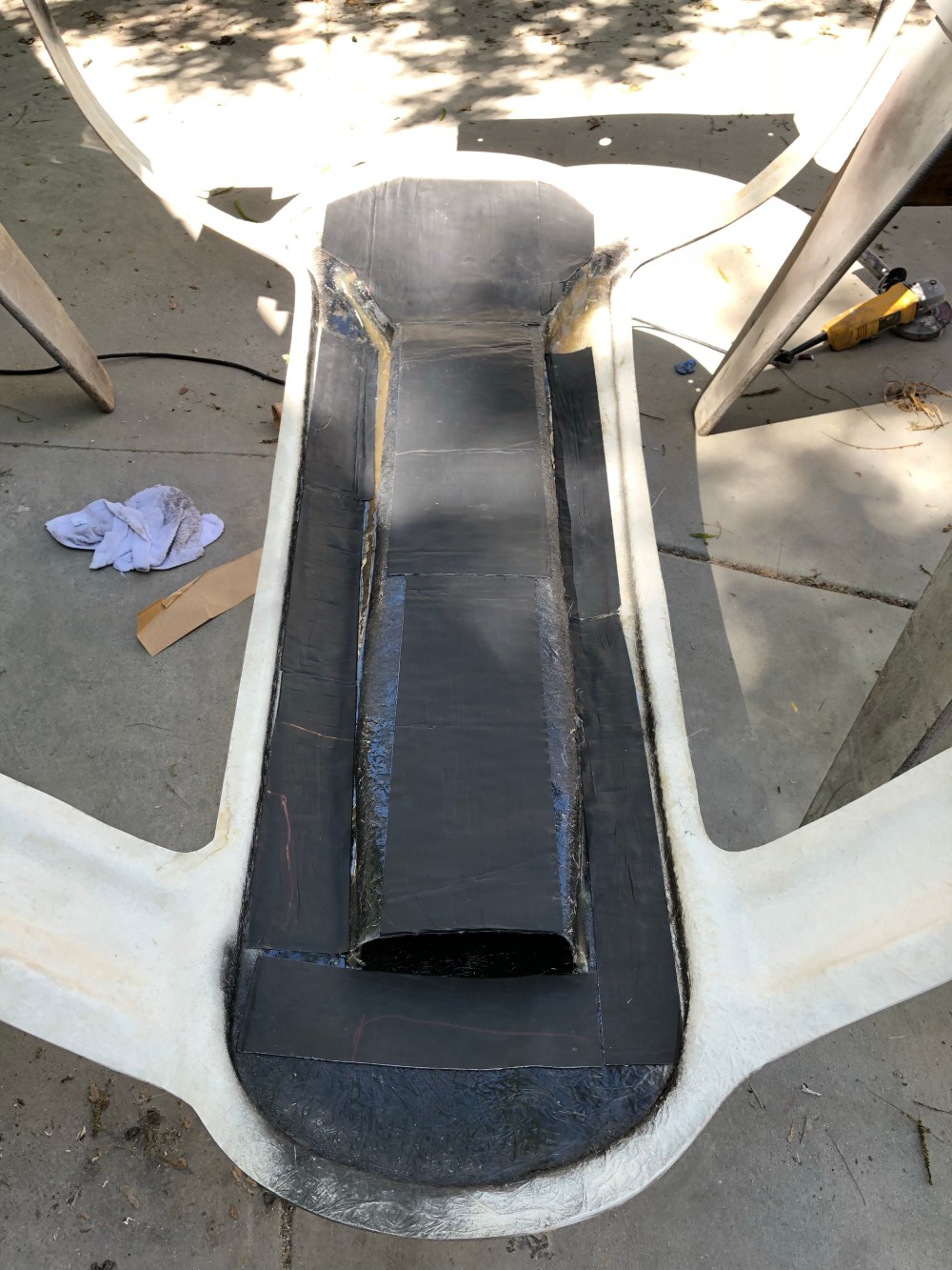
I mixed a few ounces of peanut butter and tried to bridge the gap between the roof and tunnel in a few places. There’s not enough line of sight access to fully install the tunnel; I just wanted to secure it well enough in a few locations to ensure the curve of the roof wouldn’t change the next time the body came off the car. It gets pretty messy here so I covered up my roll cage with a ton of tape to make it easier to scrape off any misplaced resin.
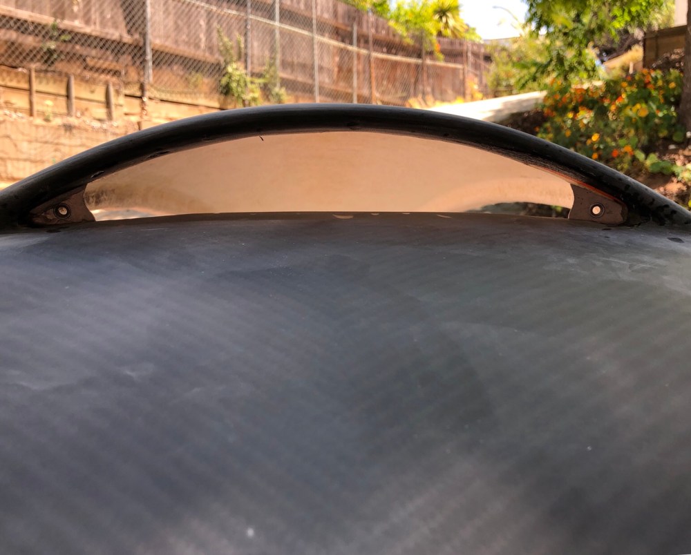
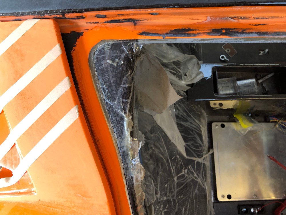
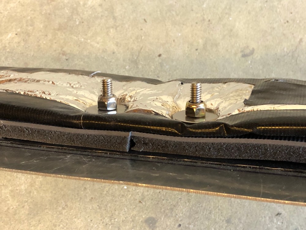
I didn’t like the look of having the roof scoop opening uncovered; I wanted to install a mesh covering of some kind. I didn’t want to bond the mesh in place because I wanted it to be serviceable in case of damage. So I bonded 2 small aluminum plates along the edges of the opening and installed threaded inserts. This will allow me to secure a piece of mesh at the front of the opening and will help give it some backing so it doesn’t “fall in”.
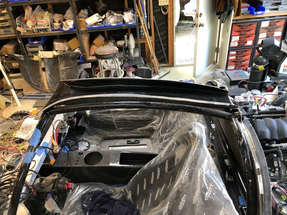
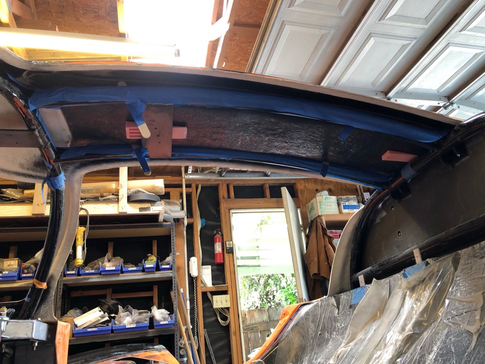
With the internal tunnel now bonded, I reinstalled the spider for some more fitting. Recall I had some delamination issues with my roof. I also had a fairly large gap between the ceiling panel and the roof. To address the delamination I simply ground out anything that didn’t look well bonded to the main structure. To address the gap, I mixed up another batch of reinforced resin and used it to bridge the gap. Before applying the resin I added a few threaded inserts I’d made so I can later screw the ceiling panel into place. The inserts were made from 10-32 riv-nuts attached to some small aluminum sheet that I’d added anti-rotation features to.
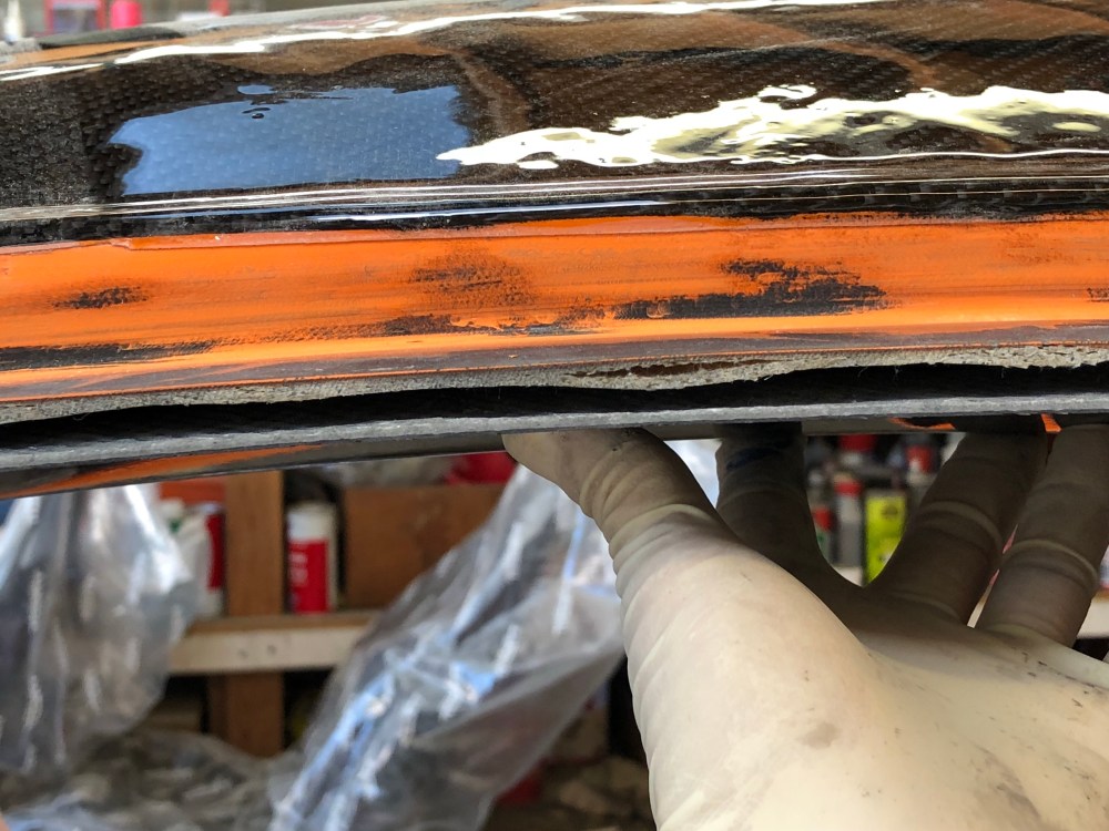


Along the aft mating edge between the spider and ceiling panel, I had some decent sized gaps to address.

I suspect the reason why my ceiling and roof panels have such large gaps is that the arc of my roof is too tall. In hindsight it might have been a good idea to strap the roof “down” onto the roll bars before glassing in the tunnel. As the attaching resin cured it may have caused my roof to further distort.
The cavity between the ceiling and roof panels will also get a layer of Luxury Liner Pro (where it fits) and some heat blocker as well. With a black roof, there’s sure to be a LOT of heat build-up inside the roof panel.
Windows:
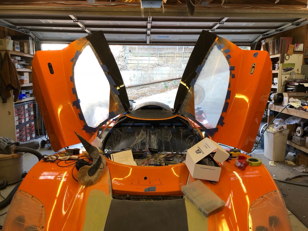
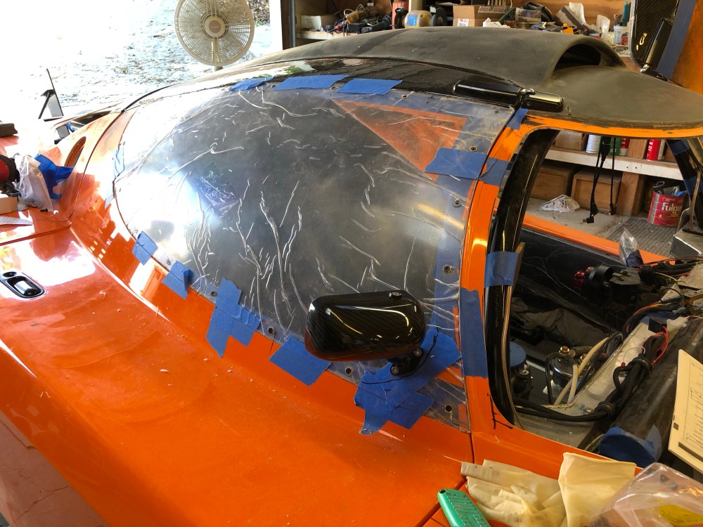
Time for more work on the exterior. I elected to go with the one-piece windows but in hindsight sometimes I wish I’d gotten the 2-piece instead. It would have been nice to be able to remove the lower window to get fresh air into the car but if I’m being honest I almost never have my windows open in my daily unless it’s to try and get hot air out of the cabin.
Fitting the windows wasn’t too difficult but boy oh boy did I sweat! Temps were in the low 90s today and I was trying to be careful about trimming too much of the window at one time – so I was going at it with sandpaper. After getting my first window trimmed and installed I had it and pulled out the belt sander – wish I’d done this before! The second window went in much quicker. I had to do more trimming than most because the upper edge had gotten shifted due to my carbon fiber patch.
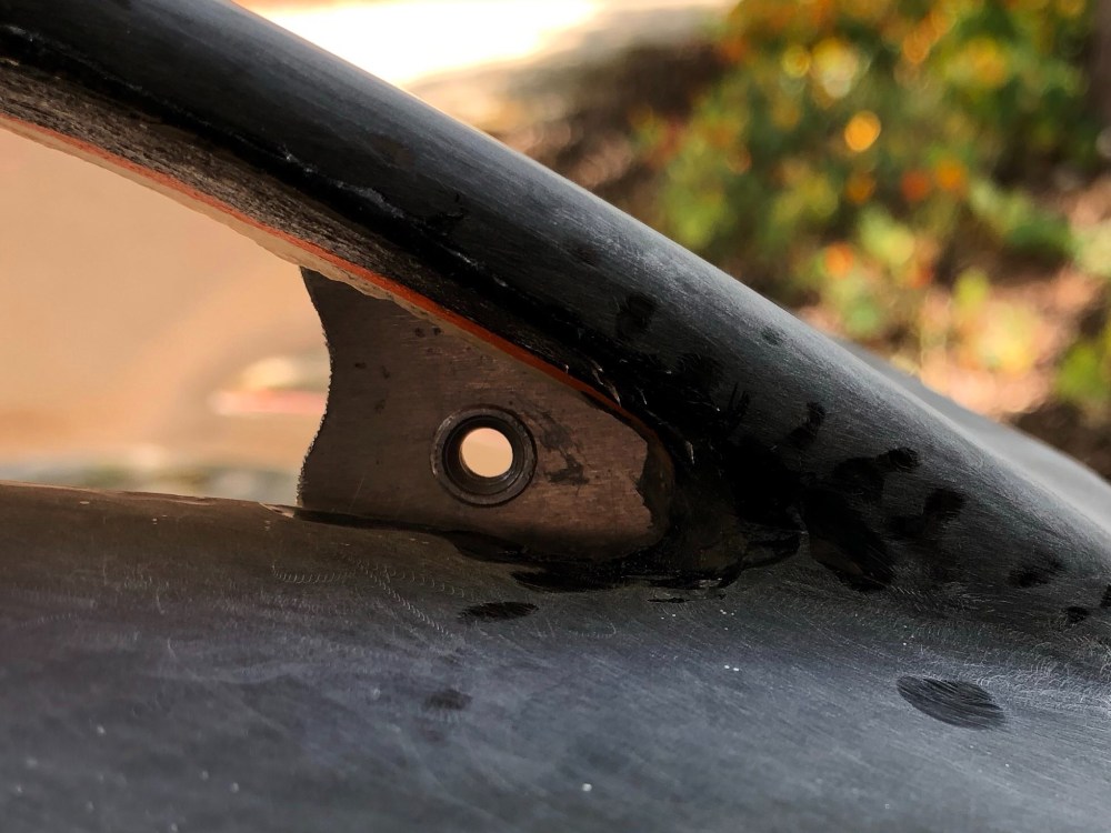
I’m using 8-32 screws to secure my windows in place. As of right now, I’ve got a small washer and nut to hold each screw in place but I’m looking for a more permanent solution that’s less of an eyesore or won’t snag someone’s shirt if they rub across a screw end. I know some folks have had pretty good luck tapping the fiberglass and running bolts right into the bodywork but I just didn’t feel good about tapping into fiberglass.

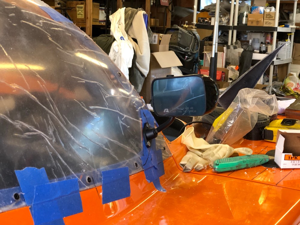
I’m not sure how functional the side mirrors are – I’ll know once I hit the road! These are the APR Formula 3 universal carbon fiber mirrors, PN CB-100004B. The carbon fiber work is fantastic and the lenses feature a slight blue tint (I think to cut down on glare).
Tub closeout panels:
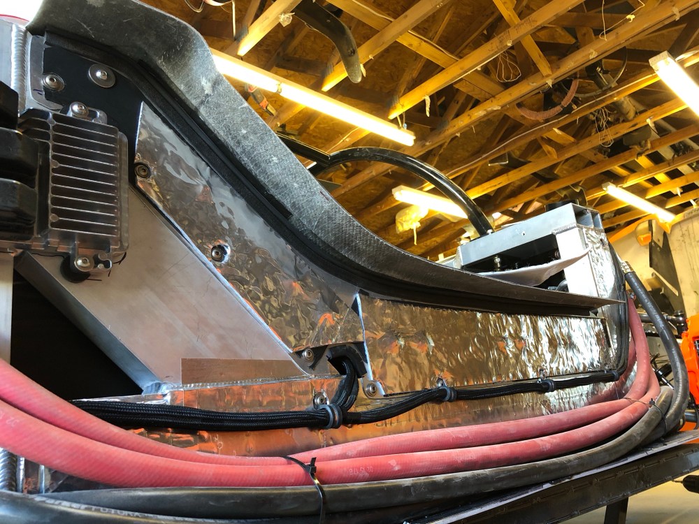
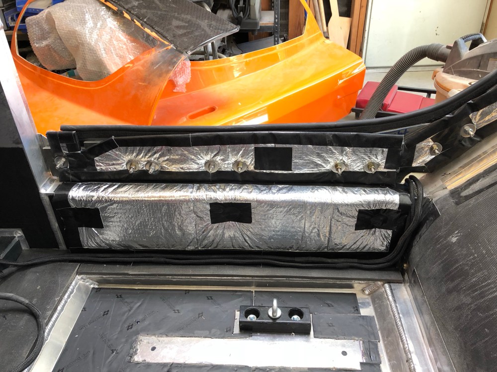
It’s my understanding that the side pods actually produce a fair amount of noise – and they’re a great source of heat considering that’s where the radiator tubes run! I felt the best solution for these panels would be to orient them vertically and attach them to the exterior of the frame rails, extending up to the underside of the tub.
Along the exterior surface of the chassis and of the closeout panel will first be a layer of Damplifier followed with a layer of Thermal Block. Along the interior surface would be a second layer of Damplifier, a layer of Luxury Liner Pro, then a layer of Heat Wave Pro. Thermal Block is more effective when facing the heat source so that’s why I elected to install that on the exterior. On the interior, heat wave pro will give me just a bit more thermal isolation and it’s less expensive than the Thermal Block.


Another closeout panel will need to be made to seal the interior off from the ~1″ gap between the forward bulkhead and the spider (that area above where the forward part of the tub’s flange ends).
Here’s what the panel looks like from the inside:


I’ll add another layer of Heat Wave Pro to the floor then top it all off with carpeting.
