I’ve been hacking away at my To-Do list. Sadly, more often than not I find I’m adding more items than I’m crossing out! To be honest I’ve been feeling pretty kicked in the shins about the project – it’s starting to really wear me down. I took a week off to visit family and hoped it would recharge me for the project but I found it had the opposite effect. The last few weeks have been pretty tough motivationally – I’m not starting the day with high energy.
As this is my first car project of this scope, I wasn’t sure what to expect – but I thought the period going from go-kart to final would be a lot quicker than this! Using rough numbers, I completed go-kart at about ~550hrs and I’m now at about ~1200hrs into this project. Doing all the mechanical work was a lot of fun and the initial fiberglassing and carbon work were really fun too. But now it just feels like a grind. I suspect it’s probably this phase where most builders find themselves hurting for motivation – especially if you’re trying to balance a full time job, family, a million other commitments, and this car build.
My next few posts will be a lot more shotgun-like. It’s difficult to try and piece together a coherent post when I’ve got so many different things I’m working on in parallel. So – I’m just going to verbal vomit (type vomit?) my progress and do my best to make my remaining posts as informative as possible for any current and future builders out there. I’m trying to stay focused on moving the needle forward one day at a time – aka, kicking the ball.
Wheel wells:
At long last – I’ve finally installed the very last piece of wheel well liner. This is the large L-shaped piece that covers the rear and inboard sides of the front wheel well.


I still need to pull the front and reinforce everything but it’s secured in its final position.
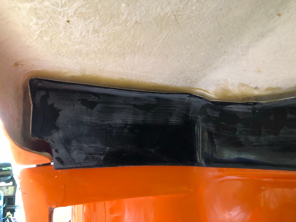
Aaargh – for whatever reason, that strange droop I had on the passenger side wheel well has returned! At a 4.5″ front ride height I get the following wheel gaps:

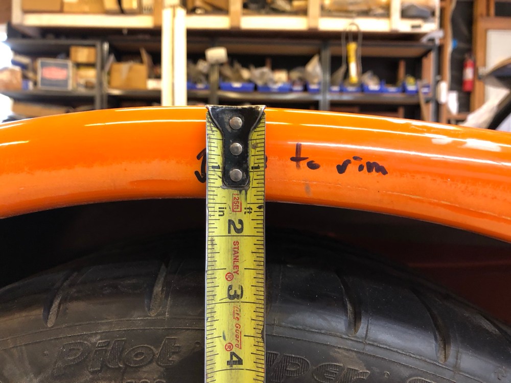
I have a discrepancy of about 1/2″ less clearance on the passenger side as compared to the driver side. There’s a flat spot of sorts along the top part of my passenger side wheel opening and my front corner sags just a touch. I shaved the flat spot to improve tire clearance – I don’t want to recontour or do anything drastic here as any changes I make will be much more obvious than the recontouring I did at the rear.
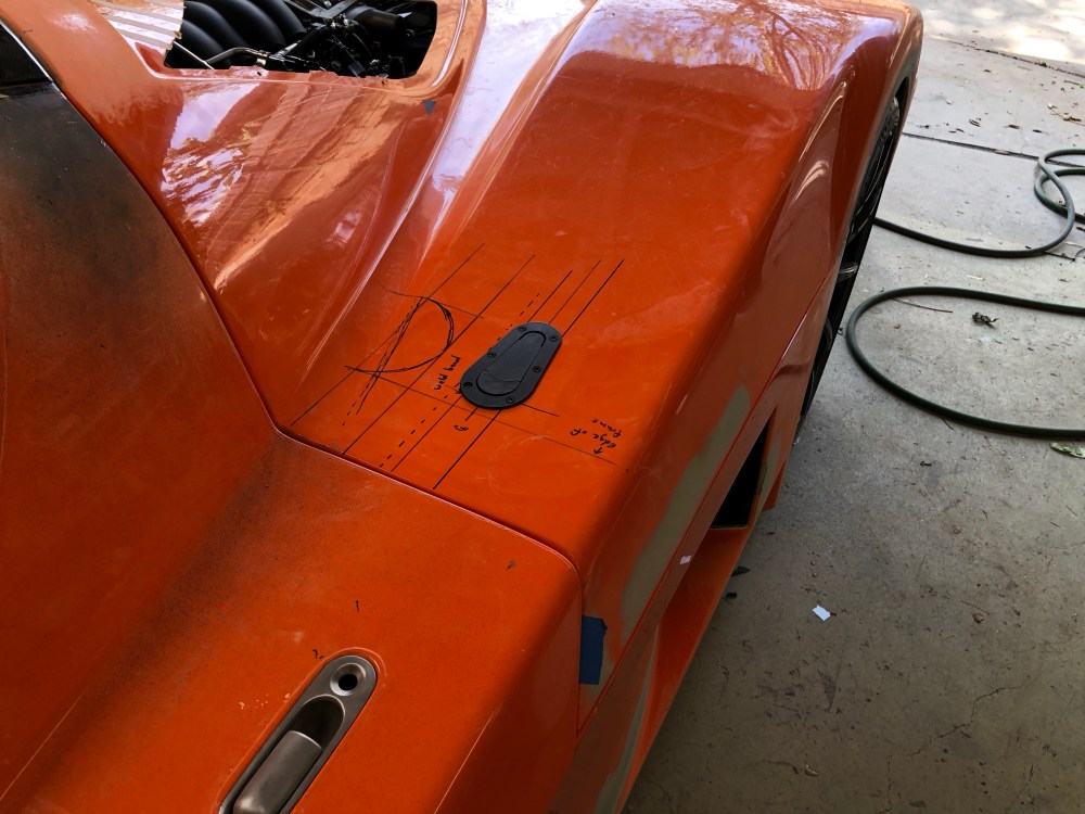
Aerocatch latches:
I have to admit – I was pretty jazzed about getting my aerocatch latches installed on my front clam. I felt like I was finally making tracks to getting the body to a state where I could do the final fitting by having the catches installed and getting the preload correct at all the body attachment points. However …
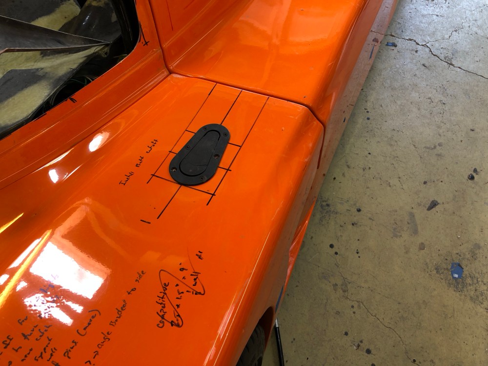

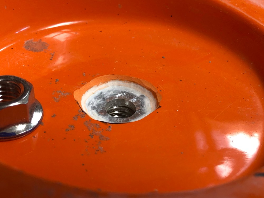

I guess there’s a reason why this is the path less traveled … for any other builders intending to go this route, keep this “gotcha” in mind. If I didn’t have enough threads my next move would have been to try a thinner jam nut. The instructions on the aerocatch state you MUST use the included rubber spacers otherwise damage to the pin may occur – unfortunately in my current setup there isn’t much room left to spare. I believe this is driven by impact loading of the pin due to shifting of the bodywork/latch mechanism. I’ll have to fashion some kind alternate rubber puck or some other damper device to mitigate against that potential issue.


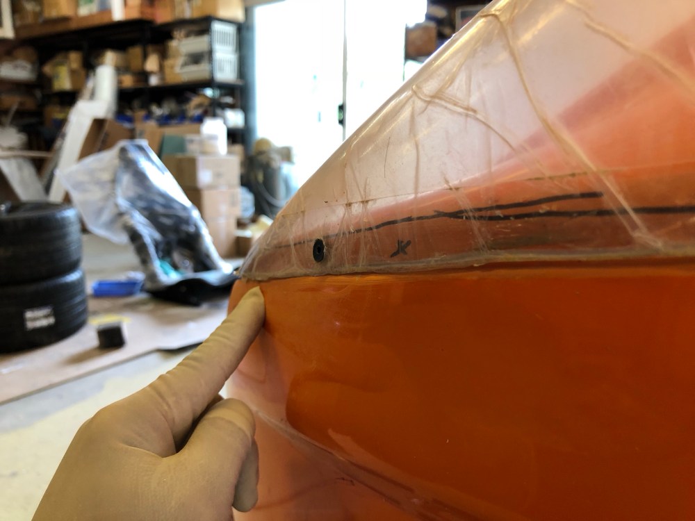
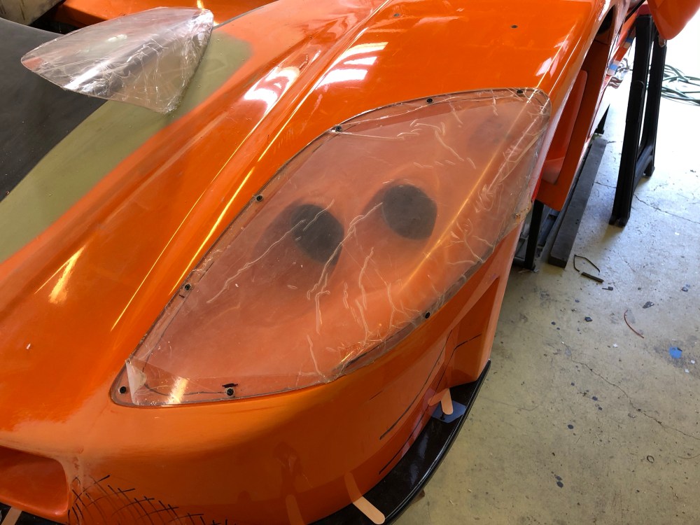
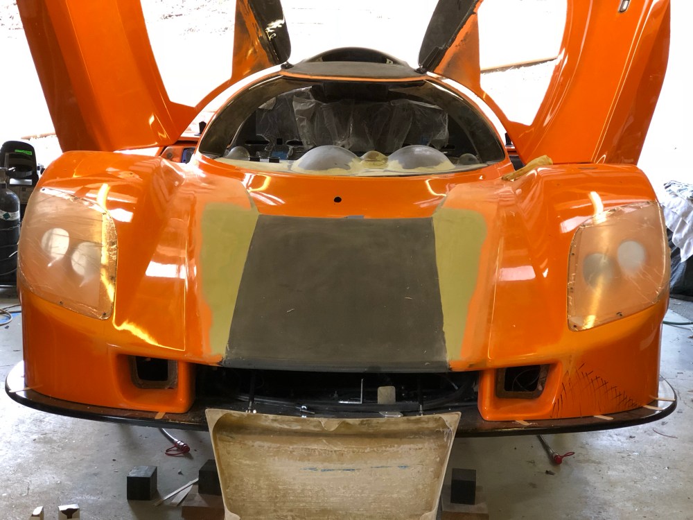
Headlight covers:
When installing the headlight covers/lenses it seemed to me the part most critical in getting aligned with the body is the forward exterior corner. The lens is made from Lexan(?) and contoured to fit the bodywork; however placement of the lens can be dictated by how the bodywork is sanded and how much shaping of the lens you care to do. As received, the lenses fit pretty well and didn’t require too much massaging. I found my driver side lens seemed to push outboard more than I cared so I sanded the opposite edge back to bring the lens inboard. To get the forward outside corner aligned, I had to position the lens as far back as possible to avoid having the lens overhang the bumper.


I considered trying to fabricate some type of seal around the covers so water/dirt intrusion wouldn’t be an issue but ultimately decided against adding this additional layer of complexity. The screws are readily accessible and removing the covers is relatively easy if I need to open them for cleaning. I don’t plan on washing the car frequently so I’m not too concerned about water getting behind the lenses.
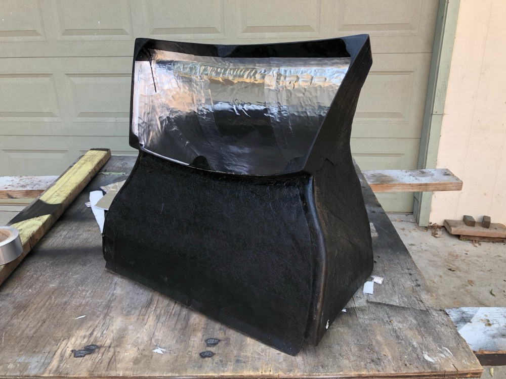
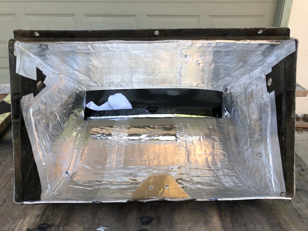
Radiator duct:
The last touches for my radiator exit duct were to paint the exterior black and add Thermal Block to the interior surfaces. This should help isolate all the heat energy to within the duct itself – I’m hoping the Thermal Block is effective at eliminating heat transfer to the brake/clutch fluid reservoirs and the passenger footbox. If the box itself stays relatively cool this should make it an effective thermal shield against radiator heat soaking back into the cabin when the car is parked after being driven.
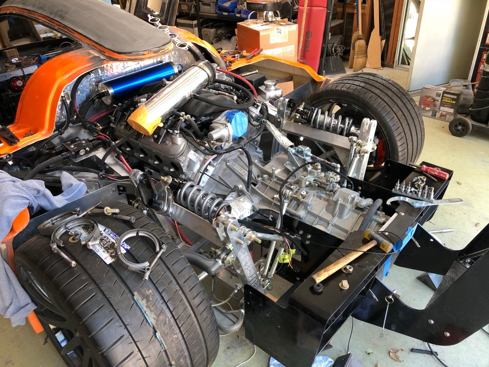
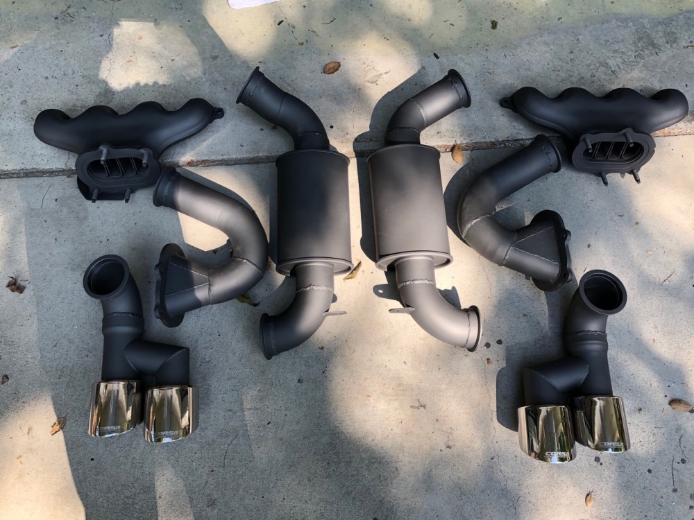
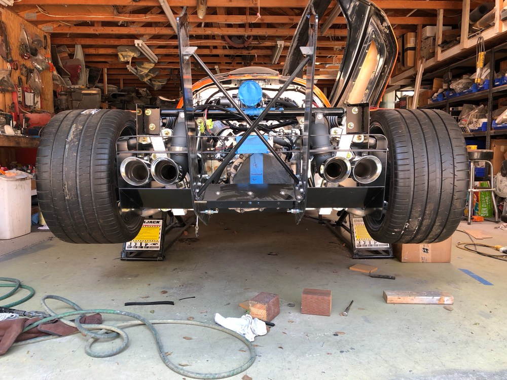
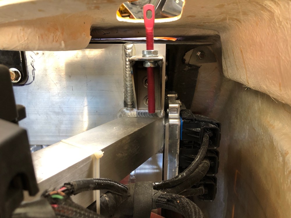
Exhaust:
In another case of 1 step forward 2 steps back, I had to remove my exhaust for ceramic coating. Space is super tight back here and there’s a LOT of stuff that needs to come out for the exhaust to be removed.