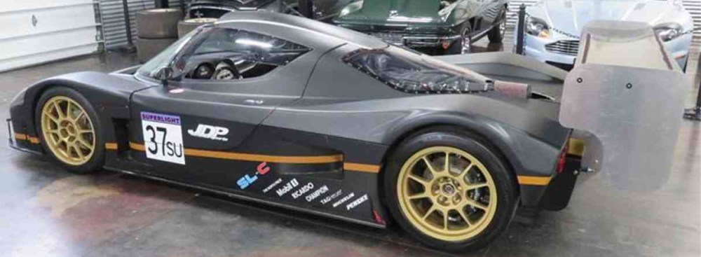
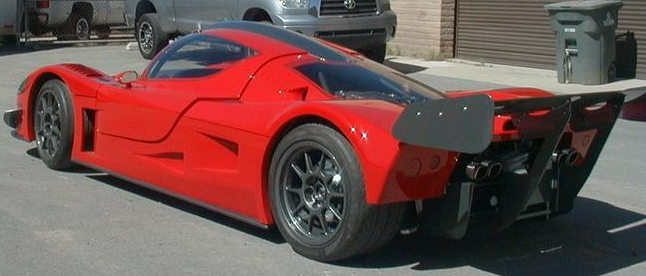
The Superlite SLC can be ordered in 2 configurations; street or race tail. The street tail incorporates a short duckbill wing to provide aero downforce. The race tail uses two tall aluminum stanchions attached to the rear diffuser to support an elevated wing. I opted to go with the race tail – I thought it looked cooler.
Diffuser mounting:
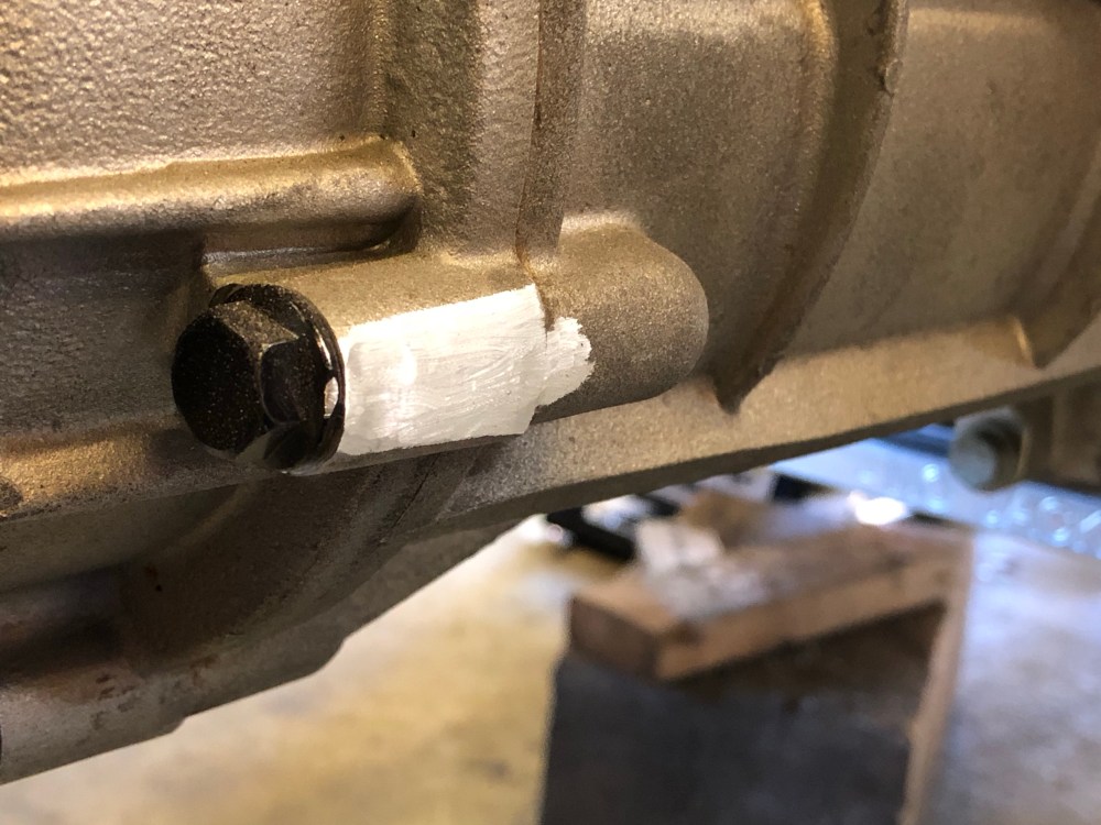
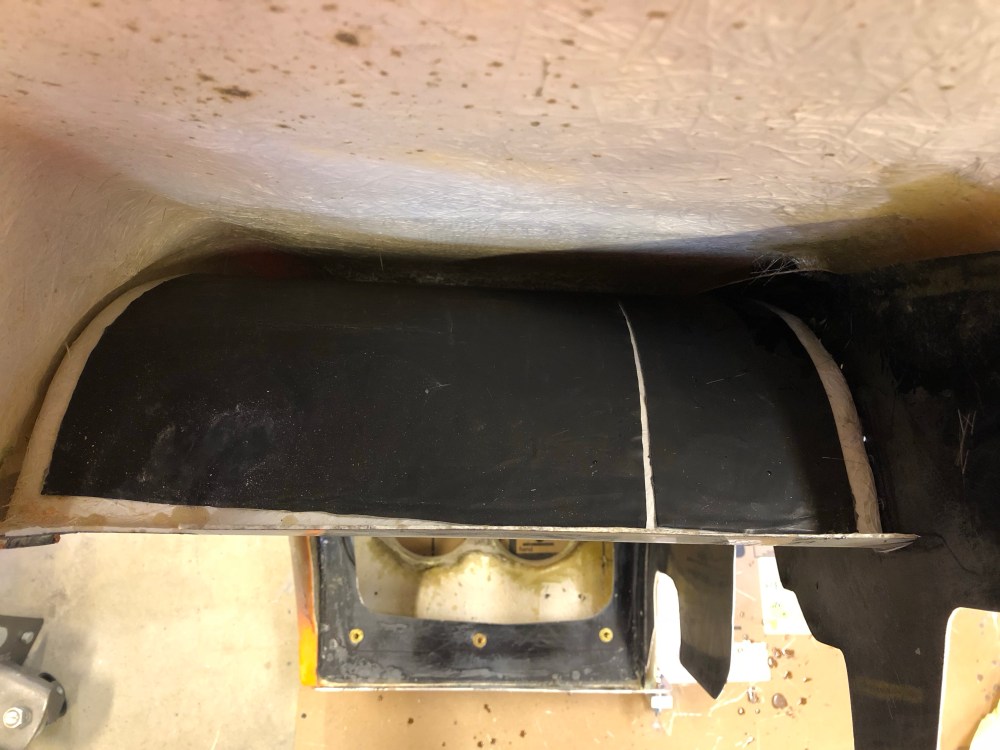
As received, the rear diffuser can’t be mounted to the chassis without modification. The lower center “wing” interferes with a good portion of the Graziano transaxle so some minor surgery needs to happen.


The RCR supplied diffuser mounts didn’t work for me. I couldn’t find an angle or orientation that worked without having to put a good amount of strain on the diffuser. The brackets were either too wide or too narrow depending how you oriented them; so the diffuser outer endplates would have to be bent one way or the other to use the factory supplied brackets – not a good idea.
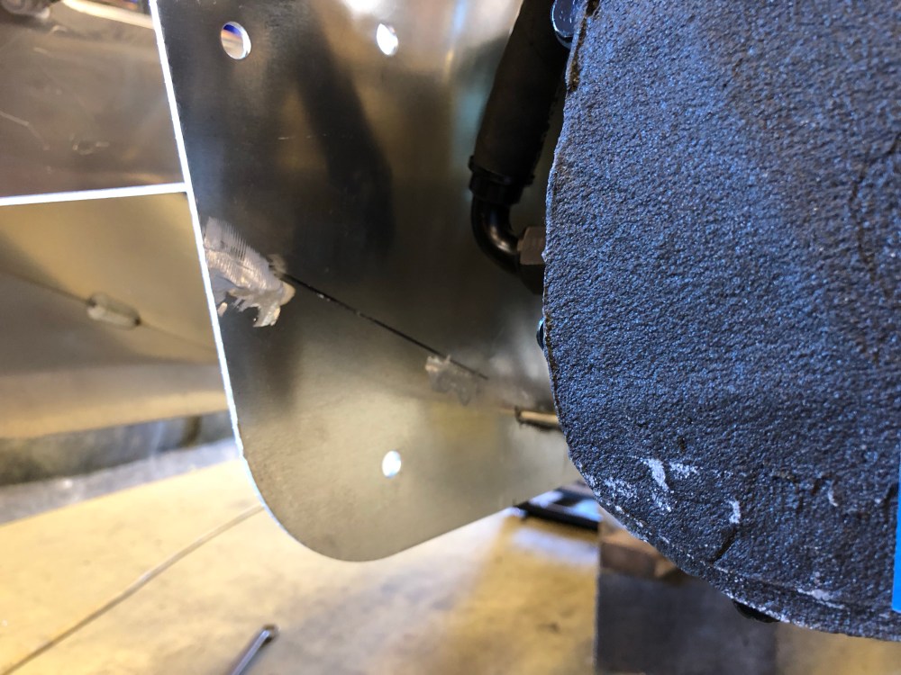
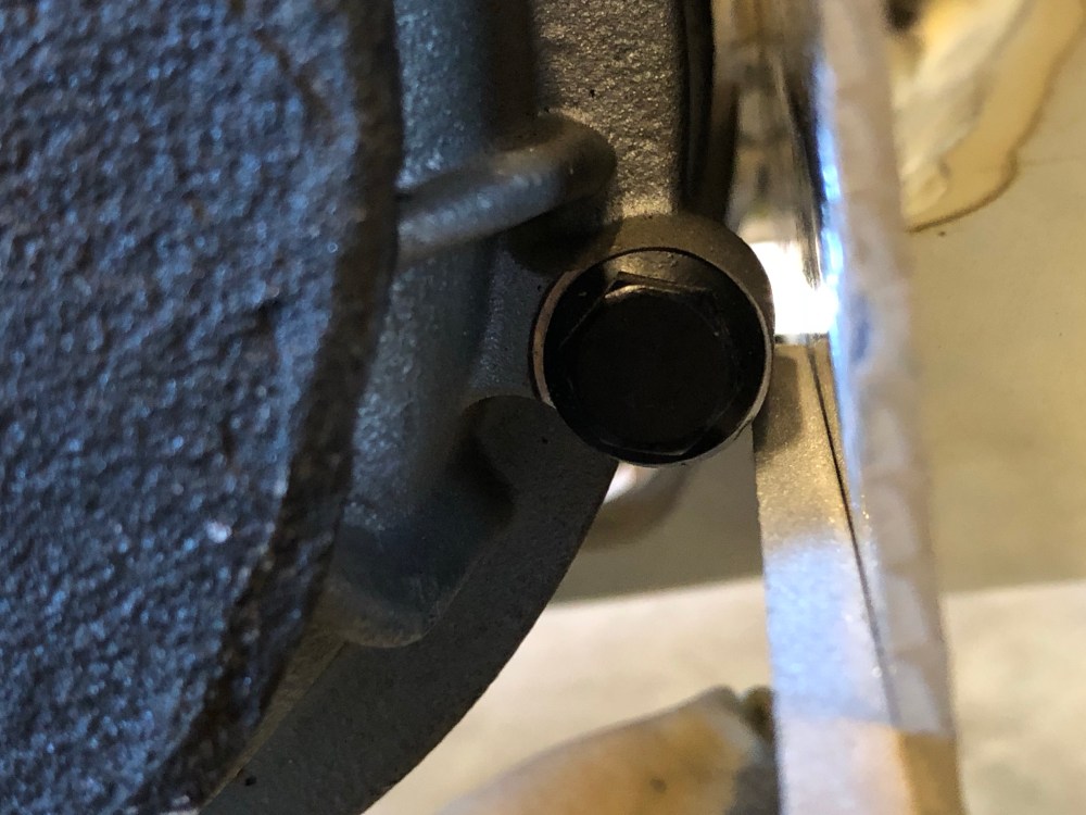
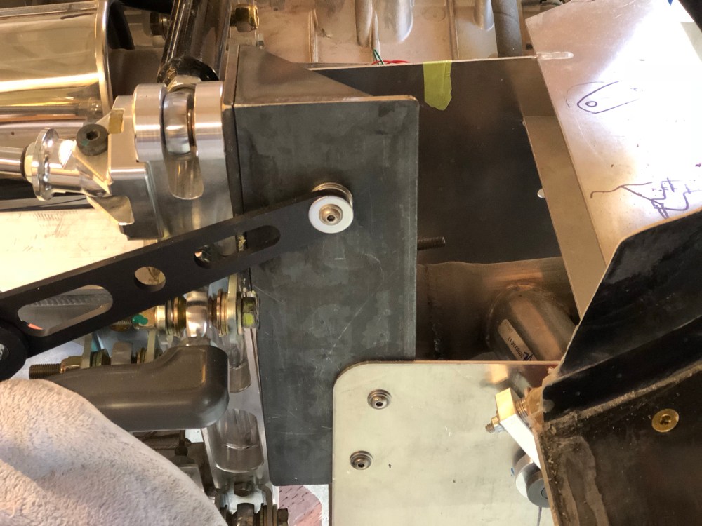
The diffuser supports the rear wing stanchions so all aero loads will be going through the diffuser and the diffuser’s central mounts. That’s a fair bit of downward force and likely a good bit of twisting – so the center area of the diffuser will need to be restrained in all axes of motion. I made a series of L-metal brackets, bolting the two center diffuser uprights to the Graziano support brackets, then another set of L-metal brackets securing the lower edge to the rearmost lower chassis brace.
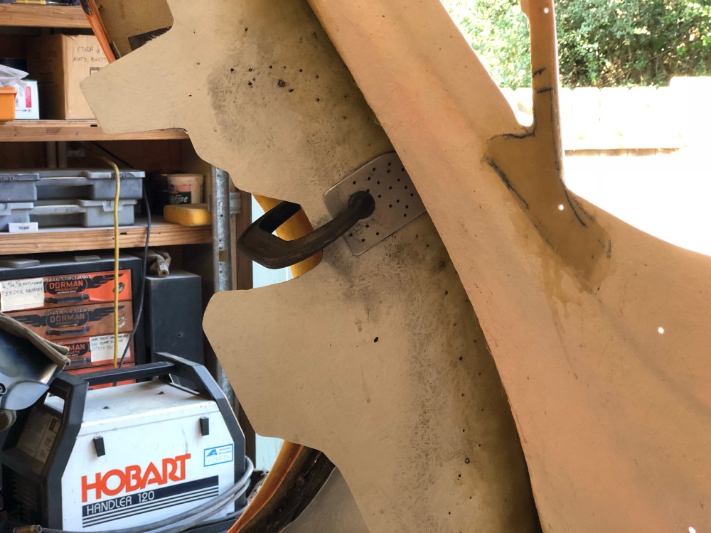
The diffuser also supports the weight of the rear clam when it’s in the open position and stabilizes it in the closed. The rear hinge attaches to the diffuser’s outermost plates; without additional supports here the diffuser ends are pretty wobbly – not so bueno. Much of the loading and vibration will primarily be in the Z-axis (vertical) so that’s what I prioritized for the endplate stabilizer mounts.
Bob helped me out with getting the endplate mounts fabricated. I wanted it to be very stiff and Bob’s welding comfort is with steel so we came up with the “beefcake” bracket. I think this takes the cake for strongest diffuser endplate mount ever on an SLC – and likely heaviest too!


An additional complicating factor is the rear clam swings open until it crashes into the rear wing supports unless the builder installs some type of restraining device. DCarter came up with a really nice setup where he used 2 folding hinges which prevents the clam from rotating too far back but allows it to swing far enough to let gravity hold it open. He used Allstar Performance hood prop PN 23620 (2 req’d, sold in singles). One end attaches to a mount he fabricated which is mounted to the rear of his engine box and another attaches to the engine side shielding of his rear wheel liners. His rear wheel liners were reinforced with aluminum; see Dan’s build thread, post #294. I told Dan I was going to shamelessly copy his cool hood prop design. My plan is to integrate the chassis-side hinge mount with the diffuser endplate mounts.
Rear hinge:
I haven’t seen a lot of detail in other build threads on how others have done this so here’s some info on how I did mine. It’s not the most sophisticated hinge but this is one of those git’r’done tasks I didn’t much care to over-complicate.
The RCR supplied hinge has a 1/4″ thruhole; at first I thought about using a 1/4″ dowel and matching drill bushing to get a really tight rotating couple. Unfortunately the sheet metal used to make the diffuser is pretty thin and I think this type of joint would need more support – so some Aluminum welding would be needed. My Aluminum expert welder (Lynn) has flown back home for the warmer months so this more elegant solution may need to wait for v2.0 of the car – or never.
Instead, I used a few needle roller thrust bearings to help reduce the friction at the hinge. I ordered the following:
- Needle roller thrust bearing for 1/4″ hole, McMaster PN 5909K23, qty 4
- Needle roller thrust bearing washer for 1/4″ hole, McMaster PN 5909K231, qty 8
I placed a set of washers and bearing on either side of the RCR supplied hinge then bolted the assembly onto the diffuser. The final assembly will be held together using a nylock nut; you can’t reef down on this bolt because too much preload will cause the hinge to bind.


To locate and drill the holes in the diffuser I first identified the driver side hole by mounting the hinge onto the underside of the rear clam and drilled a 1/4″ hole wherever the hinge ended up. To transfer the hole to the other side I used my laser to get an exactly opposing hole – any misalignment between holes means the rear clam will open cockeyed and may bind.
Pro tip: Be sure your rear clam is fully seated on the alignment pins and supported at the rear before drilling your first hinge mounting hole. Guess who didn’t do that?
My rear clam was *just* slightly off and was sagging at the rear when I made my holes. To rectify this I need to shim ~0.25″ between my rear clam and the hinge bracket. Lucky me, I was so accurate in transferring my hinge mounting holes that both sides are off by the same amount.
Wheel liner:
The next step is to install the engine side portion of the rear wheel liners so we know where one of the hinge attachment points goes.
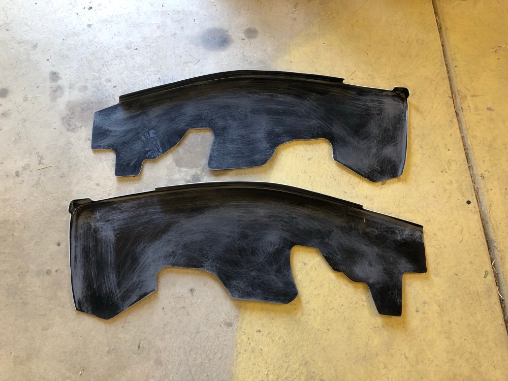
The liners won’t sit flush against the rear clam; as with most other pieces of the wheel well liners, you’ll need to trim it so you can get it as close as possible, then fill the gaps using peanut butter and reinforce with glass. Except where the vertical piece joints with the curved liner piece, most other areas have gaps which are too large for panel bond.
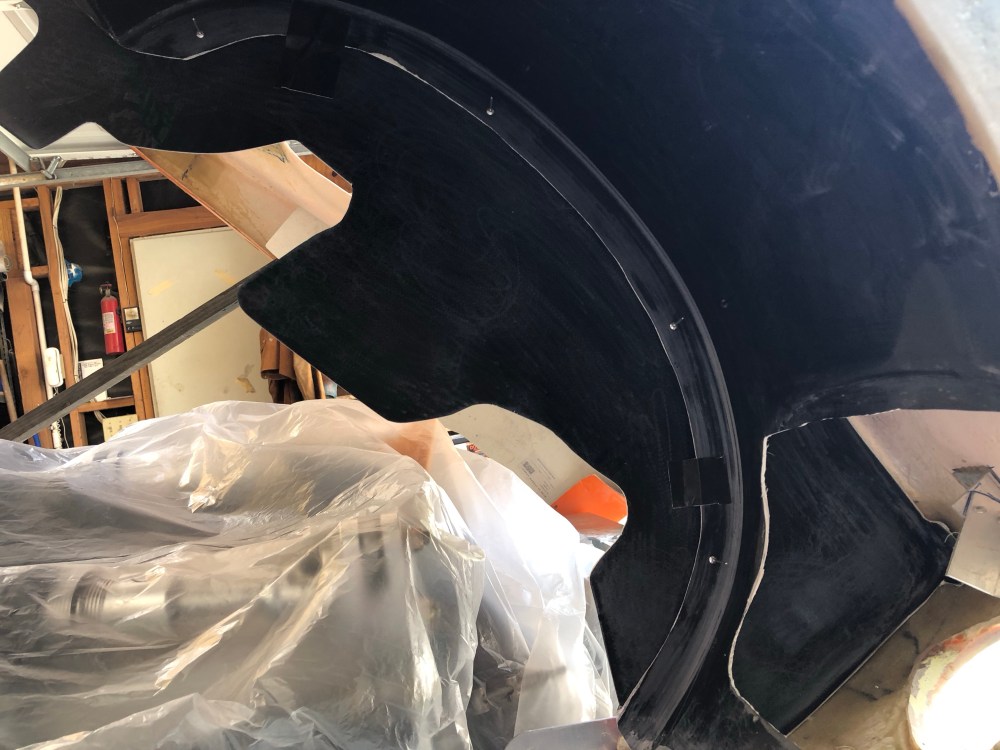
I started by using construction paper to figure out the reliefs, then transferred everything to foam core poster board for a better representation of the actual piece. After verifying the clam could open and shut without interference, and suspension articulation was good, I transferred my reliefs to the actual fiberglass pieces. Be sure to get your liners trimmed and positioned into their final locations before transferring the reliefs. Note that these vertical pieces are pretty flexy and you may want to trim anticipating some amount of side to side motion as the clam comes down. Once I verified the actual pieces were good to go, I sanded all contact points down to prep for future fiberglassing. For the joint that will be getting panel bond, I Swiss cheesed both pieces along the joint to get as much surface area as possible for bonding. I used several rivets to keep the pieces together while the panel bond was curing. These rivets aren’t expected to hold any kind of load once everything’s bonded and glassed together.
I wanted to bond the liner with the rear clam positioned and located via the rear hinge points and the forward alignment pins. There is a risk that bonding these pieces in while the rear clam is out of position may distort the clam and make it difficult to re-install. Therefore the liner will have to be secured in stages because access to all the necessary joints isn’t possible with the rear clam down.
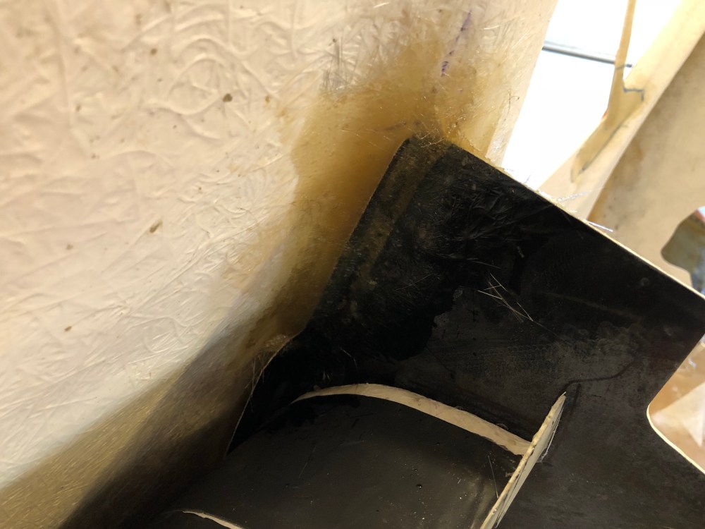
- Bond the two liners together using panel bond, hold using rivets. Use peanut butter and fill gaps wherever reach is possible. Let everything cure overnight.
- Using CSM, fiberglass all accessible areas.
- I had planned on following up with even more fiberglassing with the rear off the body but I was able to get enough of it secured that there really wasn’t any need to add more fiberglass!


Pro tip: add sound damper to the upper wheel well liner BEFORE bonding it in! It’s pretty tough to add once everything’s closed up (ask me how I know)!


YES! the last piece of the rear wheel well liner has finally been completed!!! I did a small victory dance.


- Diffuser mounted? – CHECK
- Rear hinge completed? – CHECK
- Hood prop mounted? – CHECK
So with all that work completed we’re finally able to start mounting the rear wing!
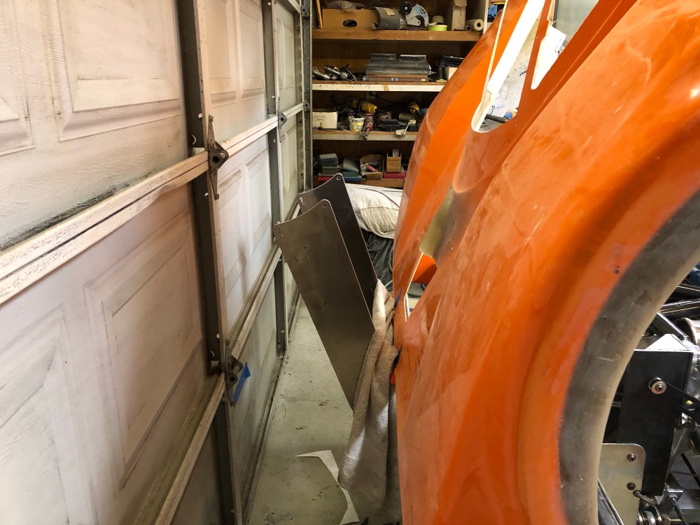
The rear wing mounts are two aluminum plates made from 1/4″ aluminum sheet. They’re way heavier than they need to be – unfortunately they’re just not very stiff. Without any additional bracing the wing flops around quite a bit – doesn’t seem like a good idea to leave it as-is.


There’s a pretty wide range of stanchion braces folks have come up with over the years – not to mention a pretty drastic change in the supports themselves. The most basic is a single rod that extends from one plate to the other and from top to bottom. This is a nice, straightforward way to give the stanchions additional lateral stiffness – push the wing left or right and that single rod does a pretty good job of keeping things where they should stay. Unfortunately it doesn’t do much in the twisting department.
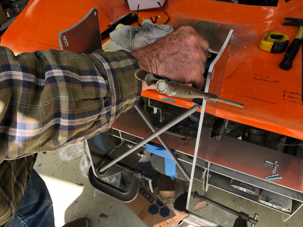
2 is better than 1? Yep. I took our brace design just a slight step further by adding a second bar. This really stiffens things up laterally! But won’t this design suffer the same twisting issues as a single bar? Yes – theoretically … Having a second bar provides a lot more anti-twisting stiffness in one rotation, but doesn’t do much for the other – or does it?
After we fabbed up our 2 bar brace it actually seems like the twist resistance is pretty high – but not quite enough for my taste. I added another 1/8″ aluminum plate and tied the two lower ends of the bars together, effectively boxing out the lower end of the wing supports. The wing itself boxes out the top part – so starting very close to where the stanchions turn upward, my supports are fully boxed and cross-barred. The stanchions are now super stiff – the only flex or motion I’m getting now is at the mount itself.
The options here are less ideal. I would like to secure the wing supports using quick release pins so I can remove them and open the rear cover without needing a tool – y’know, in case of an engine fire or some other event that would necessitate a speedy opening. The trouble is that means 2 of the 4 anchor points needs to be removable without any tools, leaving only 2 attachment points per stanchion. These anchor points can’t be so preloaded/tight that the plates won’t move by hand. Using the same washer/thrust bearing setup as I have for the rear clam hinge, there’s still just a little slop that I can wiggle the wing back and forth just a smidge.
But I think it’s OK.
With the car parked and just sitting there, it’s not an issue if it can wiggle back and forth a bit. With aero loading, the wing assembly loads rearward and what little slop there is goes away pretty quickly; I think I can live with that.


I may come back and try to lighten these stanchions by cutting away material in the centers but that’s a future project likely never to be completed.
- Wing installed? – CHECK
Last bit – the wing endplates! The carbon wing has aluminum plates bonded at the very ends for structural stability. To help keep air flowing over/under the wing as it should, larger endplates need to be added to the wing. The latest version of the endplates is pretty chunky; it’s 1/8″ aluminum plate and pretty large. I suppose it’s more efficient because it’s super big and catches more air – but I think it’s a bit ugly; function over form in this case. I like the smaller, more shapely aero looking pieces used on older builds. I reached out to some of the old timers for help and HJones was nice enough to send me a template for his endplates – thanks again Howard!
I was a bit concerned about people cutting themselves by accidentally bumping into the endplates. 1/8″ aluminum is pretty thin and even with some careful sanding it’s difficult to get a large enough radius on the edge to make it safe to handle. I decided I would make my endplates from laminated fiberglass. I could make the plate thicker while keeping the weight less than the equivalent in aluminum. I also didn’t want to add too much mass at the very edges of the wing – makes it even more prone to wobbling.

Phew – that’s a LOT of work just to mount the rear wing!
