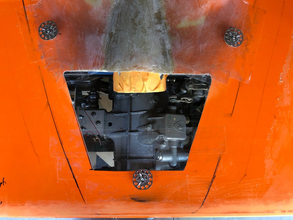
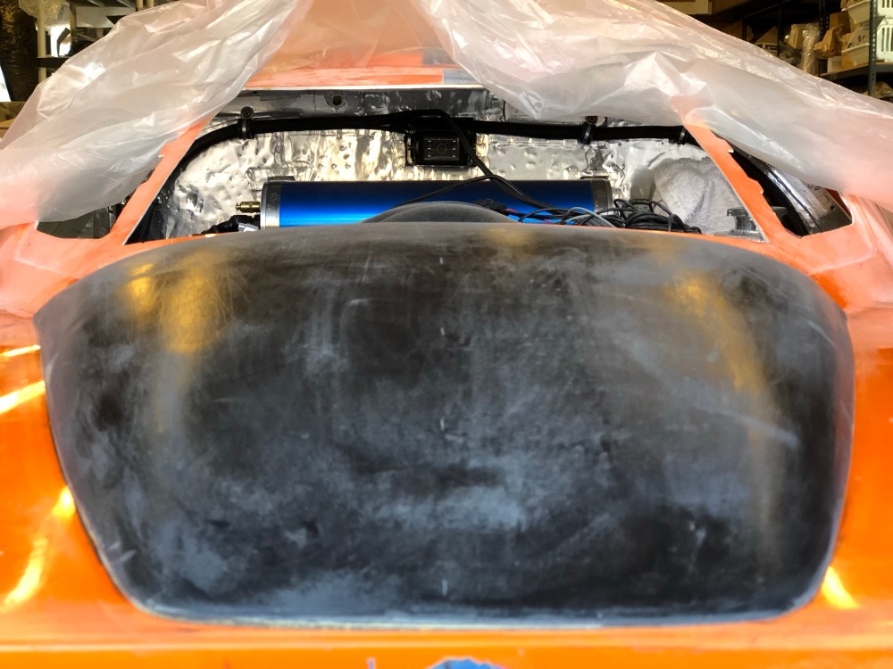
If you’re building an SLC and you’ve opted to go with the race tail one of the more popular modifications is to add a fresh air scoop at the back of the car to feed your air filter. Placing the air filter right below a center-mounted scoop is especially popular for those running LS based motors as the throttle body is just an almost-straight tube away from the filter. Unfortunately the required 4″ tube will most definitely not clear the race tail and a hole must be cut to accommodate the tube and air filter.
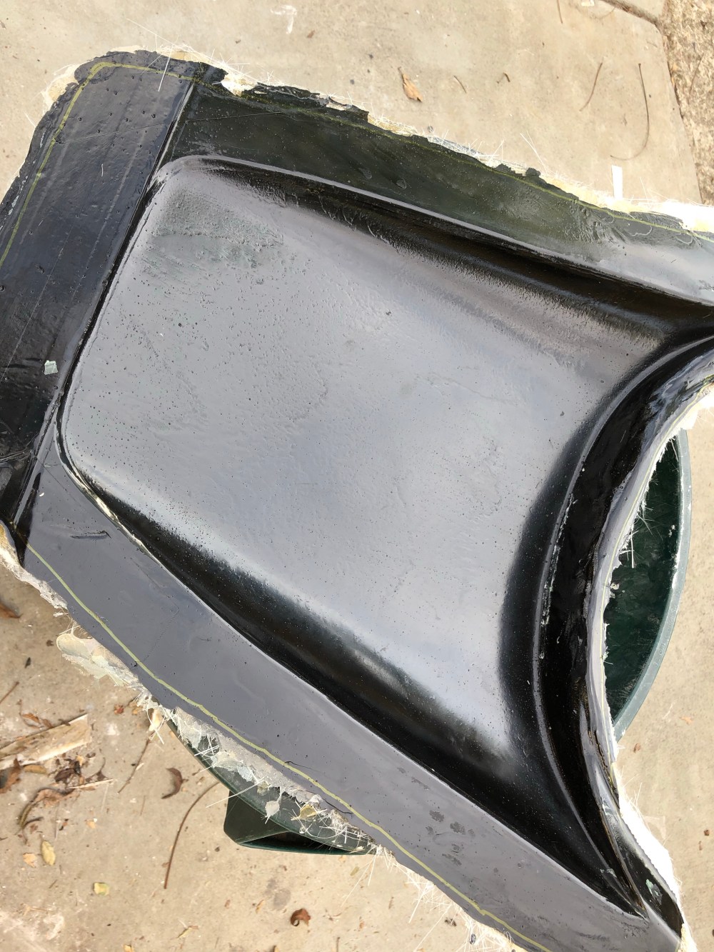
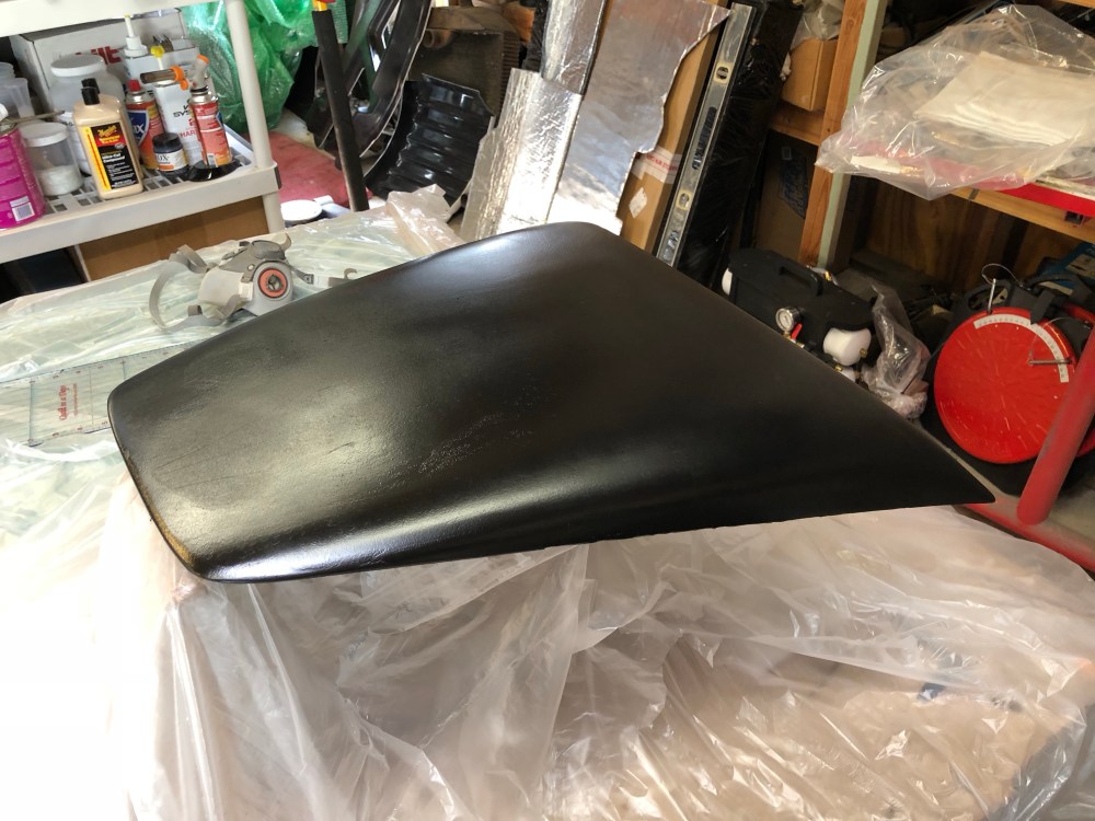
I purchased a scoop for use on my project; unfortunately there was some asymmetry in the part that was driving my OCD completely bonkers.
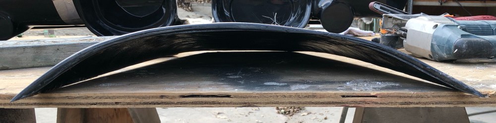
To bring this side back up I added several layers of fiberglass mat and added bondo to smooth it out. By the time I was finished I think I’d added about 1/4″ of material – a bit more than I’d expected when I first started recontouring the scoop. I decided it’s time to learn how to make a mold and make my own part!
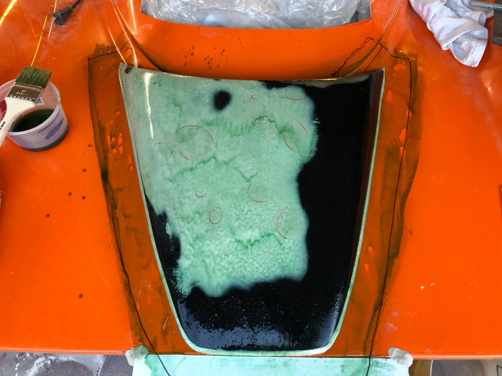


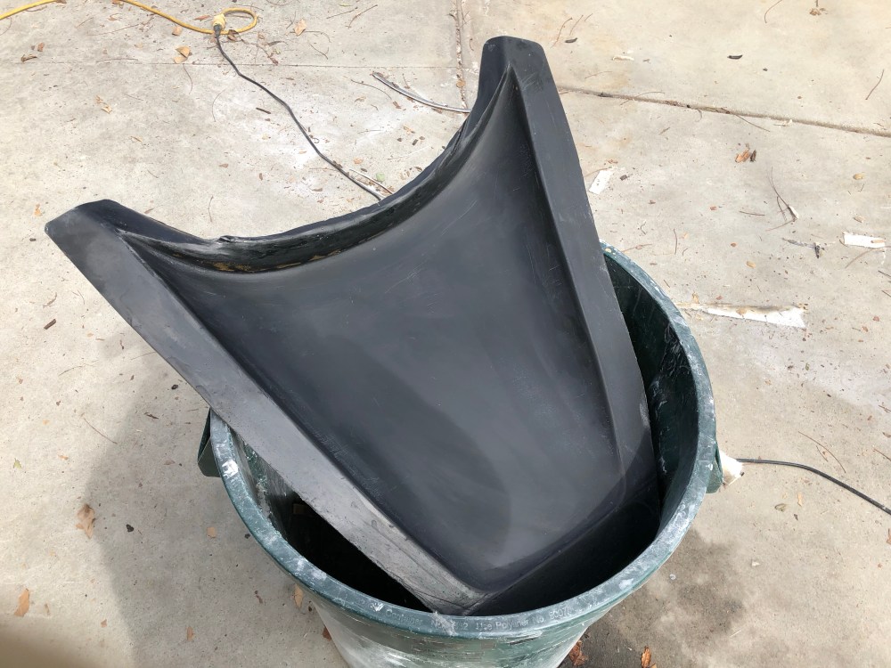
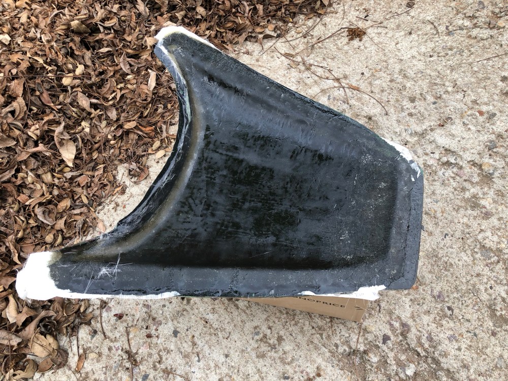
Once again, the part was relatively easy to remove from the mold – phew! Just a few stabs with a wedge and that characteristic POP! of release. Nice … I was pretty relieved to see that many flaws from the mold didn’t actually transfer over to my part. Here again, the PVA filled a lot of the minor imperfections while making new ones (yay). The net result was a pretty smooth intake scoop. The gelcoat layer will gave me sufficient material to knock down most defects to get it smooth enough to quiet down that OCD that was screaming at me before.


Even after all that work to even out the intake, I found I needed to add just a smidge more bondo to my new scoop to get it symmetric left to right. Next, I had to come up with a way to secure the scoop to the bodywork. I had originally considered bonding the scoop directly to the gelcoat but decided I’d rather have it removable. It’d be a lot easier to replace if it somehow got damaged in the future.
For as many build threads as I’ve read through, and as much internet sleuthing as I could do, this isn’t an area that’s really been discussed. On builds where the scoop wasn’t directly bonded to the bodywork, it seems many builders run fasteners through the top of the scoop and secure via nuts. I didn’t like how the fasteners were visible so I thought about bonding studs or bolts to the underside of the scoop. Not having a lot of experience bonding fasteners to fiberglass, I wasn’t sure what the best way would be to ensure proper alignment and holding strength. More internet searching on fastener bonding and I still came up empty.
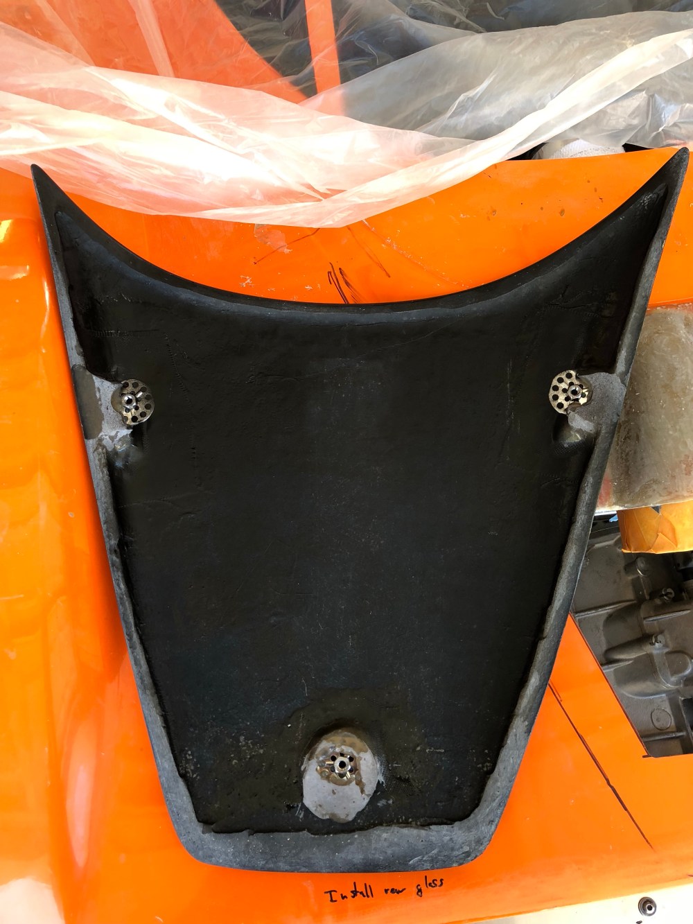
So I went way basic and just glued nuts to the underside of the scoop. I picked up a few adhesive mounted nuts from McMaster, PN 98007A029. These stainless steel nuts are welded to a perforated flange. You can bond the nuts onto a flat surface by laying down a thick layer of glue and pressing the nut into place. My strategy had to be a bit difference since I want to float these nuts in space and bond then onto a surface that’s off at an angle. Bonding them directly to the scoop meant my bolts would have to be driven at a very extreme off-plane angle relative to the bodywork – doesn’t sound very stable to me.
I placed 3 nut assemblies on stacks of washers on the rear clam and verified there was sufficient clearance for the assembly under the scoop (there’s not much room as you approach the edges!). Once located, I marked each position and drilled 1/4″ holes. I installed bolts from the underside of the rear clam and secured each washer stack/nut assembly in place.
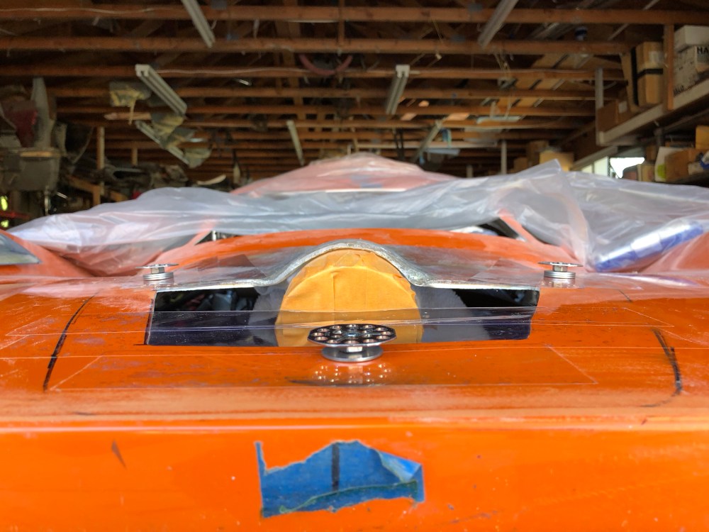
I placed washers between each nut assembly and the bodywork so I could create a gap, and orient the nut so it stayed parallel to the plane through which each bolt will pass. The gap will be used so I can provide preload to the intake scoop – I’ll adjust the thickness of the washer stack to adjust the amount of preload at each location. This will help get the scoop to sit down snuggly against the bodywork.
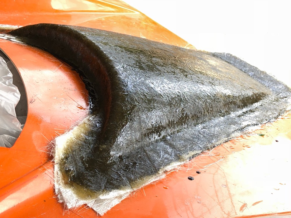
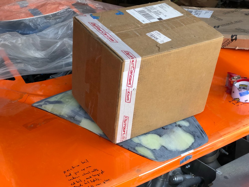
Next, I mixed up a batch of reinforced resin peanut butter and slathered a good bit around each nut assembly, making sure I squeezed resin through the perforations means it’ll hold the nuts in place and provide some anti-rotation strength as well. I then placed the scoop on the bodywork and added a few pounds to keep the scoop in place while the resin cured.
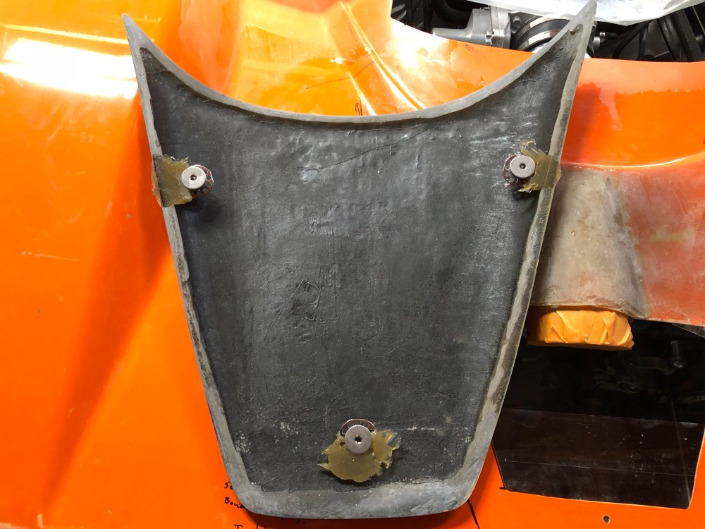
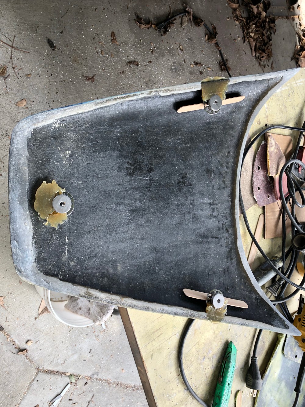
Once the scoop was free I went back in with more resin to beef up the mounting points; I also threw down a strip of glass cloth at each location – belt and suspenders!
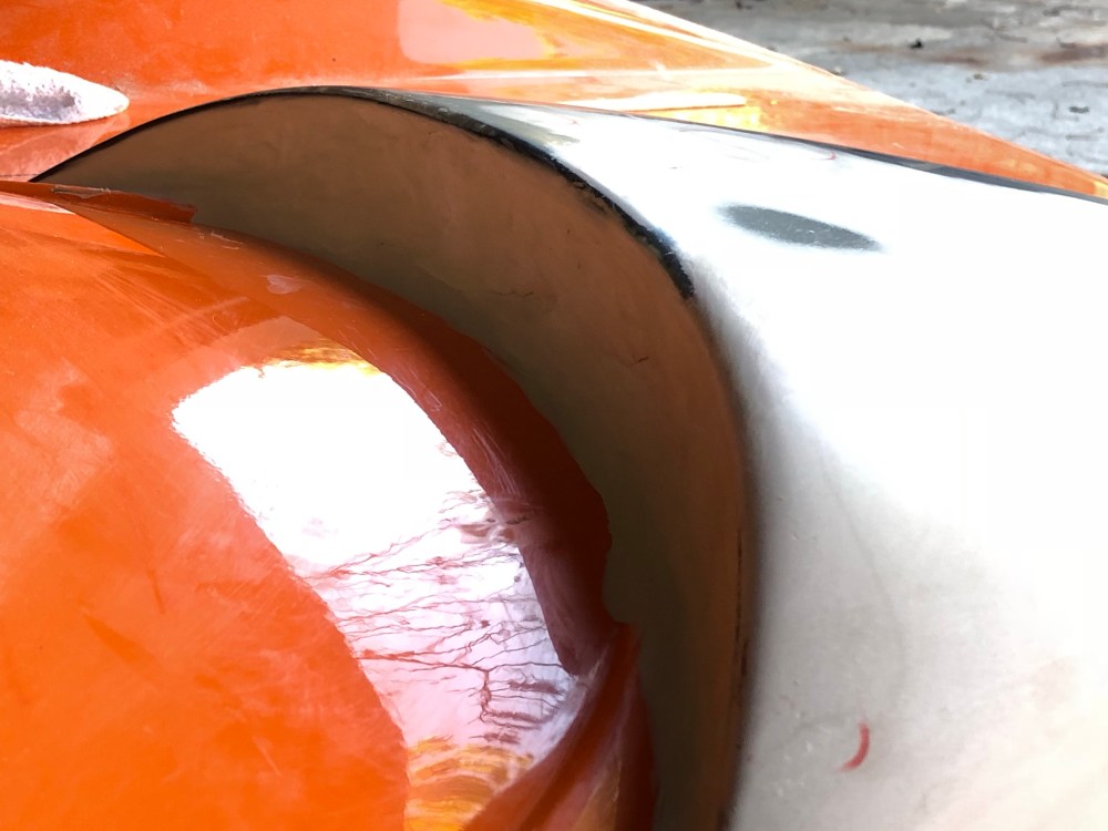
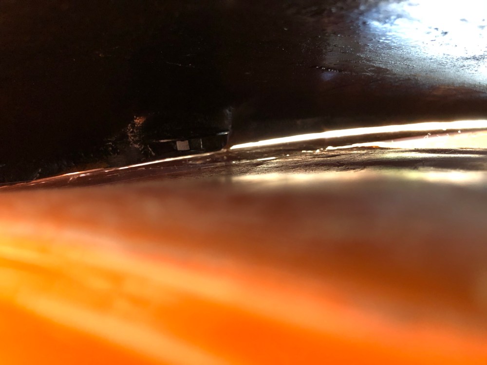
OK, mounting nuts bonded and secured! I then needed to go back and get a better fit between the scoop and the contours of the bodywork. I had roughed the edges and they were pretty good, but if you poke your head down and look into the scoop it’s clear you can see gaps between the scoop and bodywork. There’s some amount of air that’s going to spill through these cracks – and I don’t think that’s a big deal – but I thought I could do a better job to get a really flush fit.
I applied a fresh length of packing tape all along the areas where the scoop makes contact with the body. I then mixed up another batch of reinforced peanut butter and applied a thin line of it all along the mating edges on the scoop. Next, I turned the scoop over and attached it to the body using my newly anchored nuts and let the resin cure.
A little bit of sanding and voila – a perfectly flush fitting scoop with invisible fasteners!


- Intake scoop symmetric? – CHECK
- Intake scoop mounting complete? – CHECK
Now to make it pretty! I found myself staring off into the distance and my jaw went slack … it took me a moment to realize I was mumbling “car-bone …” over and over.

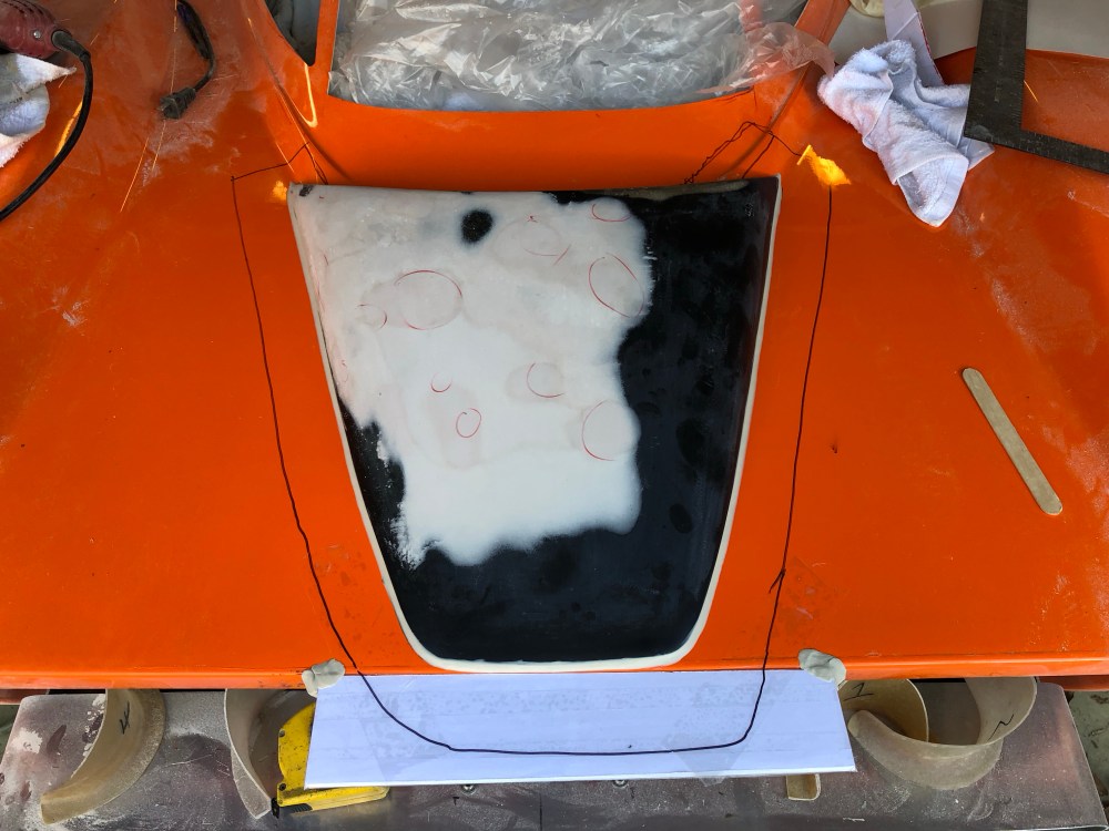
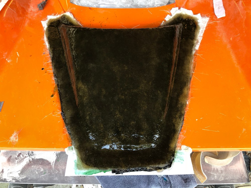
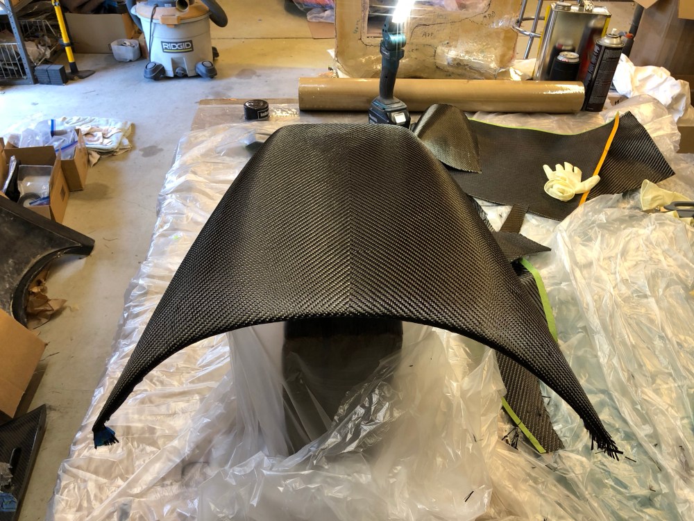
Having learned from my prior mistakes with aligning this particular weave of carbon, I decided to try a new approach to laying down the cloth. I transferred a straight line down the center of the intake using a sharpie pen. With plenty of light on hand, I then rolled the carbon cloth down onto the scoop making sure to set the center strands down along my sharpie line as the cloth touched down. Since the scoop is now shaped and sanded to size, I wanted all surfaces and edges to be as perfect as possible. I grabbed the carbon cloth and tightly folded around each edge and taped it along the inside. This will address any bunching or pull up along the finished edges and allow me to apply resin all the way up to the visible edges. Getting a really nice and consistent wet out coat along the leading edge was going to be difficult so I figured this would be the most critical area to get a good wet out coat so I don’t sand back into the fibers.

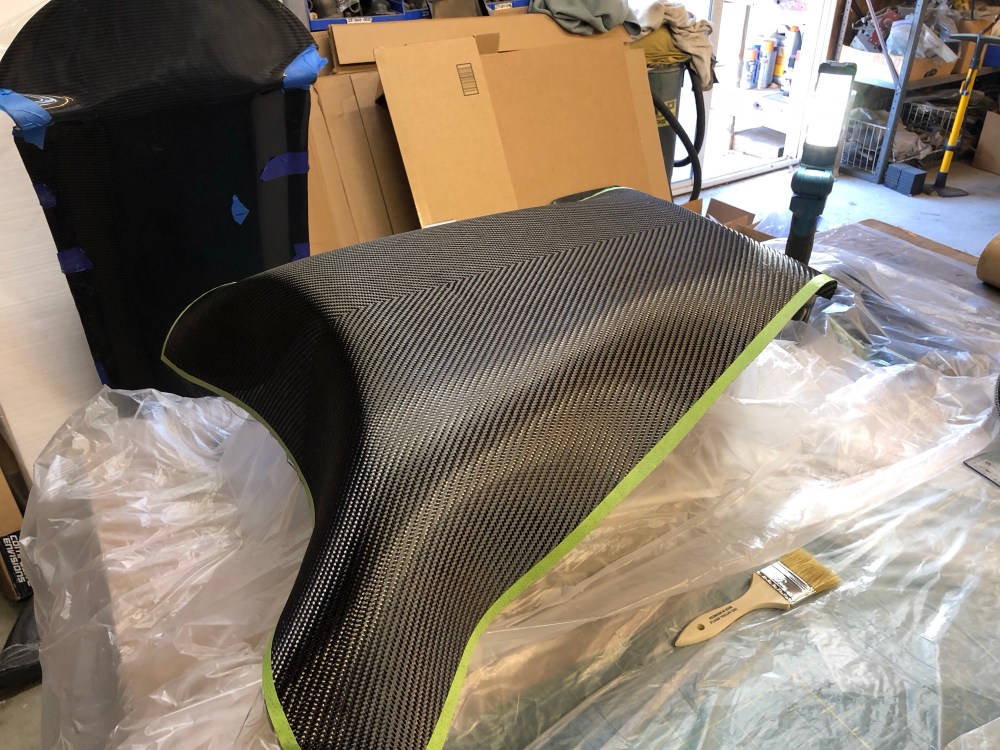

To fixture the scoop for coating, I set it on a stack of 2x4s to set the orientation of the scoop so the majority of the surface is horizontal. This will help keep the resin from flowing off the part before it can gel. The more vertical contours will be thinner, but this can be addressed after the final coats of epoxy are applied. One of the benefits of skinning carbon is the carbon sits below the surface; so any light or reflections coming off the piece will be largely determined by the epoxy contour, not the cloth contour. The upshot is minor surface irregularities of the part itself or minor variations in epoxy thickness will be obscured.
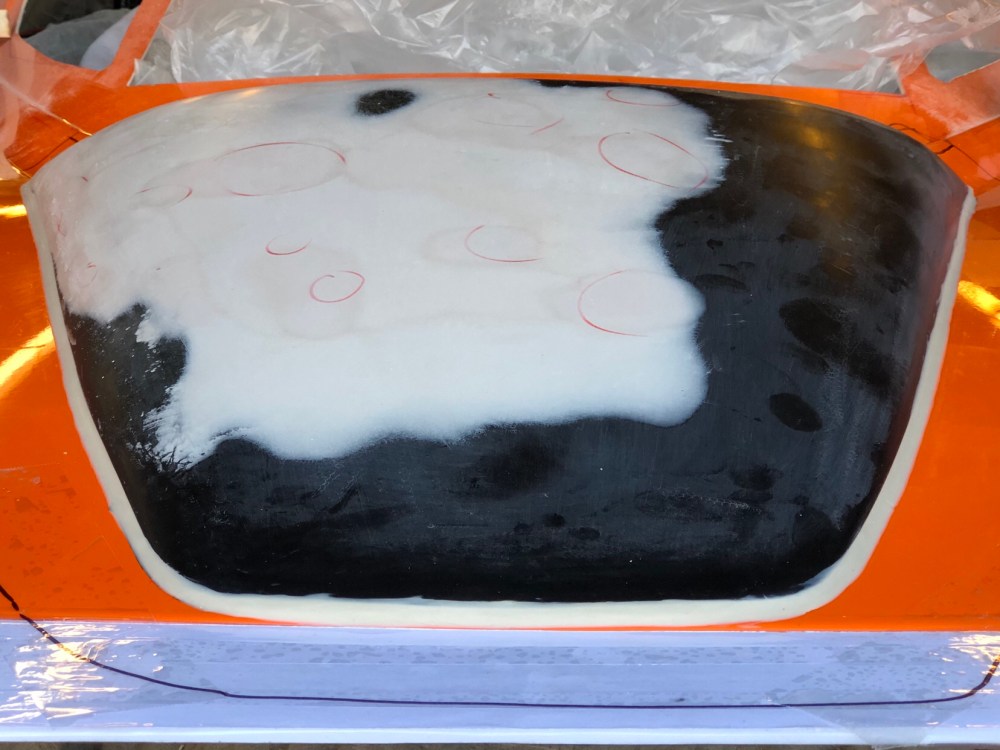
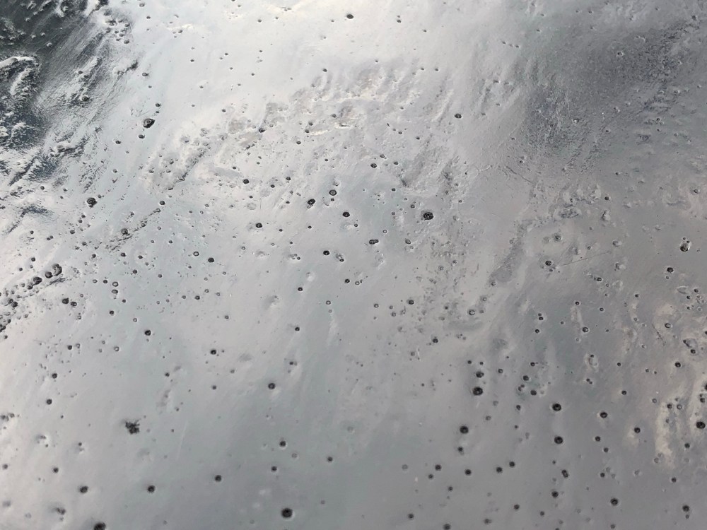
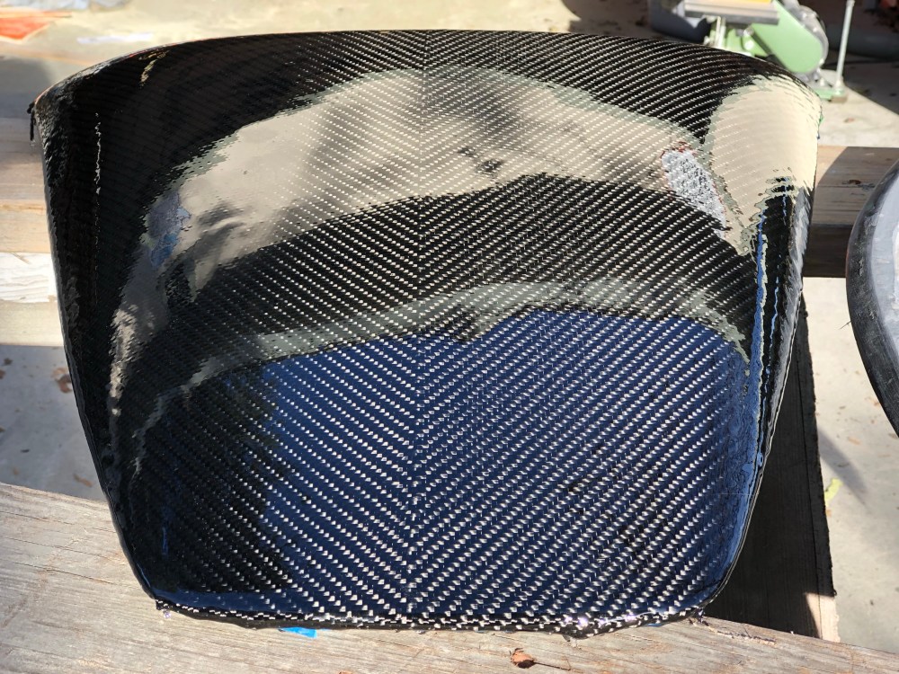
Weave variations however …


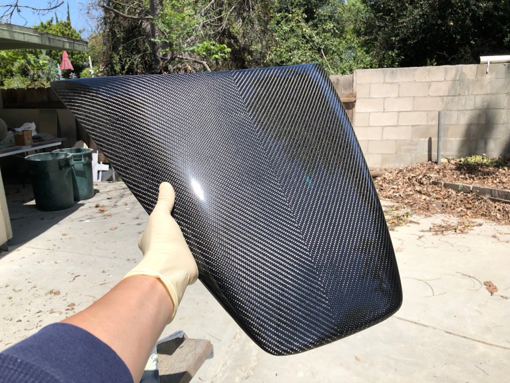
It’s absolutely INCREDIBLE how your eyes can pick up even the tiniest flaws in the weave. Our eyes are so well developed at picking out changes in patterns that just the slightest change in how light reflects off the carbon draws our attention. The good thing is – once the resin goes on the gloss and color that develops totally overwhelms a good majority of these flaws and they become unnoticeable.


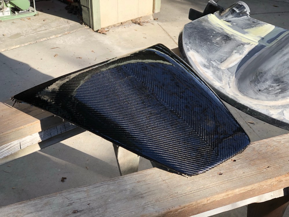
Boy, talk about lessons learned. I thought I had done an awesome job of taping everything back and securing the weave. It seems the resin flows really well and a good bit of resin got in under my tape via capillary action. When it came time to grind back and remove the excess cloth I had a pretty difficult time differentiating between the parent material, the carbon cloth, and the epoxy resin. It made for a pretty tricky clean-up of the wet out coats. I was eventually able to get it sanded back so the intake sits flush against the bodywork once again but it took way more effort than it should have – lots to learn to this skinning thing. Those YouTube videos I watched make everything look so much easier …
After letting the resin cure for a week I hit it with 220, 320, then 400 before applying about 5 coats of clear. I’ll let it cure for another week before sanding it to remove any orange peel then a polish to get it mirror smooth.
In summary – this intake scoop project has been a HUGE learning process for me. I’ve gained a ton more insight into working and making fiberglass molds, using gel coat, wet layups, and skinning carbon fiber. One of the things I really set out to do with the SLC was to push the bounds of my comfort level and learn new things (while buying new tools of course). Composites has always been a black art for me; while I don’t claim to be an expert – or have much ability beyond novice level – I’ve definitely pulled back the curtain quite a bit and peeked into a really cool field/hobby. I plan to pursue more of this kind of stuff in my spare time. The SLC is always in need of more car-bone!
