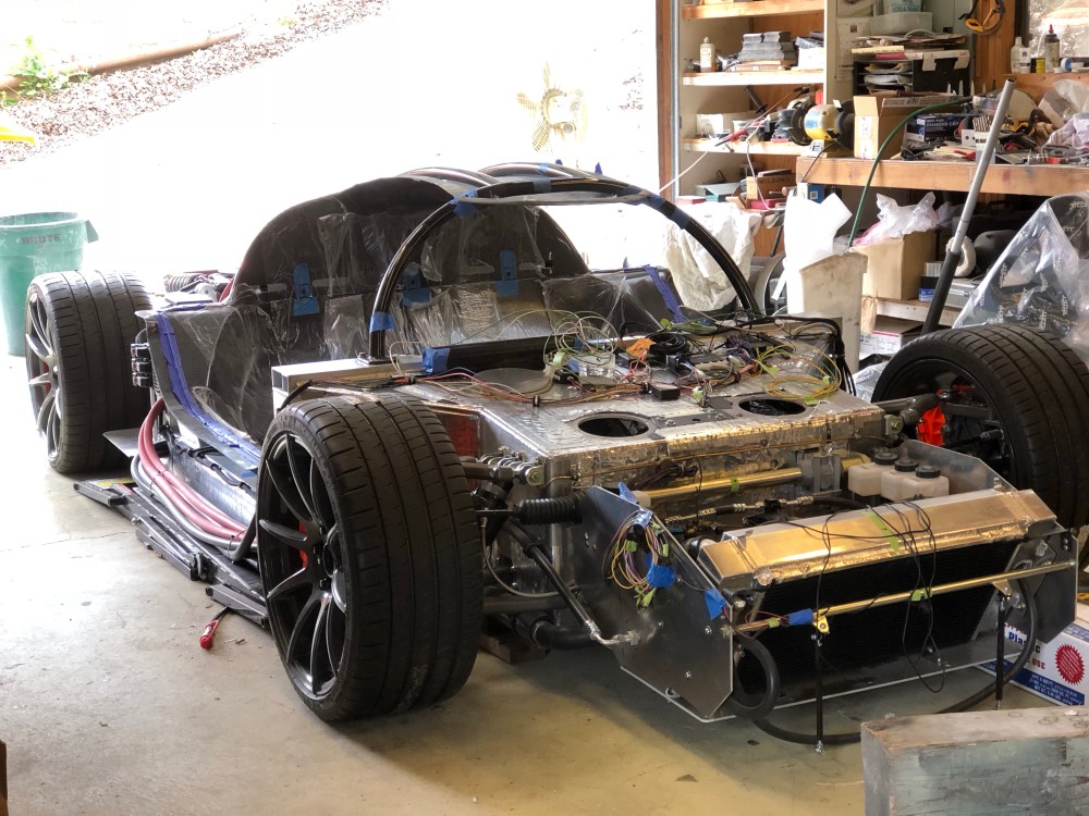
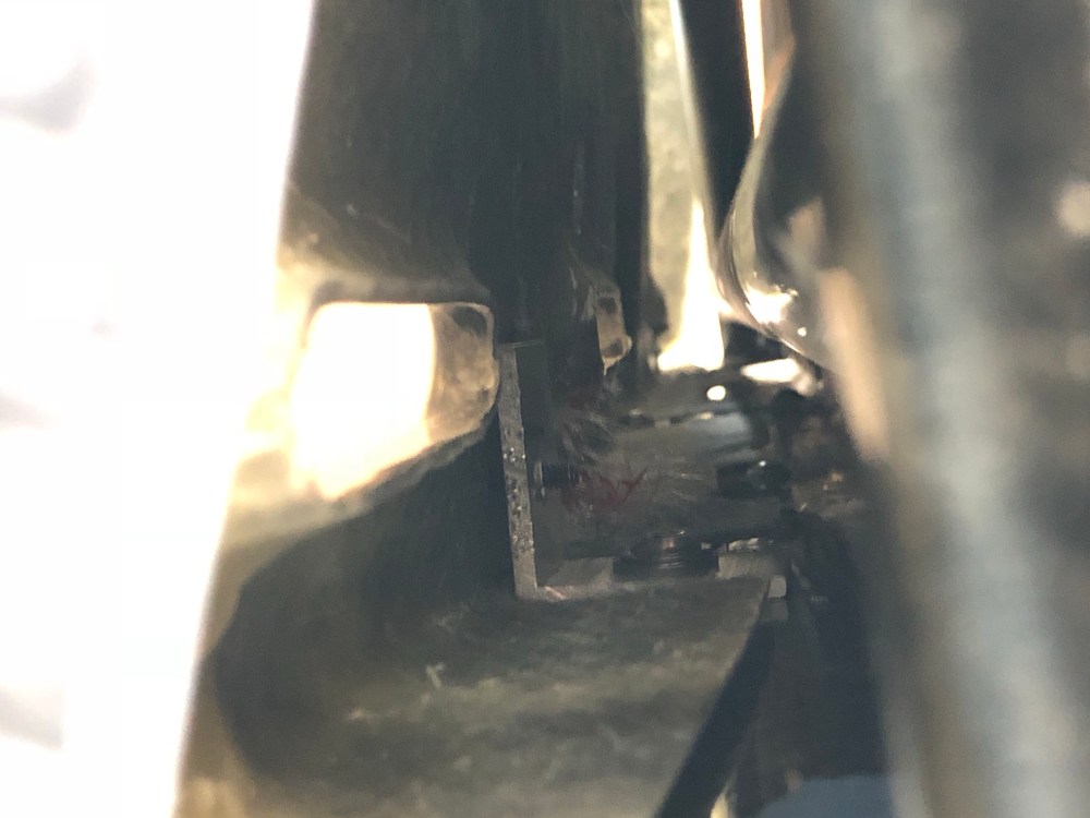
The tub is the master key to the body fitting puzzle. It sets how the spider sits relative to the chassis, which sets where the front and rear clams are positioned. Way back, I had positioned my bodywork relative to the chassis by shifting it forwards and back until I was able to achieve the best wheel well gaps (fore/aft gaps). Once I had the position of the spider figured out, I pulled everything off and installed the carbon fiber tub. The tub can float forwards and back to some degree. I then set the spider back onto the chassis and positioned it using the marks I had just made prior. The tub and spider lock into each other along the rear outer edges of the tub and along the exterior flanges. With the tub positioned relative to the spider, I marked then drilled/tapped holes to pin down the tub.
As you can see – you can’t simply drop the tub into the chassis and start fastening it in place; get it wrong, and your spider won’t sit right – which means neither will your front and rear clams. The tub is the key.
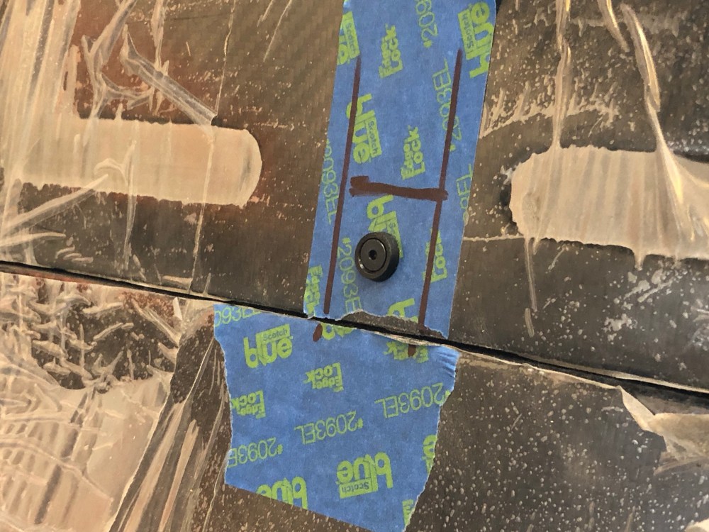
I really struggled with figuring out a cool way to secure the upper tub panel. I originally wanted to keep the interior fastener-free – nothing visible as to how it’s all held in place. Well, I sat around and thought about how I was going to secure the tub pieces and all my fastener-free solutions were way too complex, expensive, or time consuming.
Screw it. Literally. I decided I’d let this one go and have visible fasteners in the interior. Oooh … I’ll bet there are guys out there reading this right now who’re shaking their heads because they’ve gone through the exact same thought process/experience.
Now that I’d accepted my fate the solution was really simple. A couple of L brackets secured to the top of the lower tub and a few screws into the upper panel will lock the upper and lower halves together. Simple.
I haven’t quite figured out how the ceiling panel will be secured to the car. That’s an adventure for another day, I’ve got bigger fish to fry today!
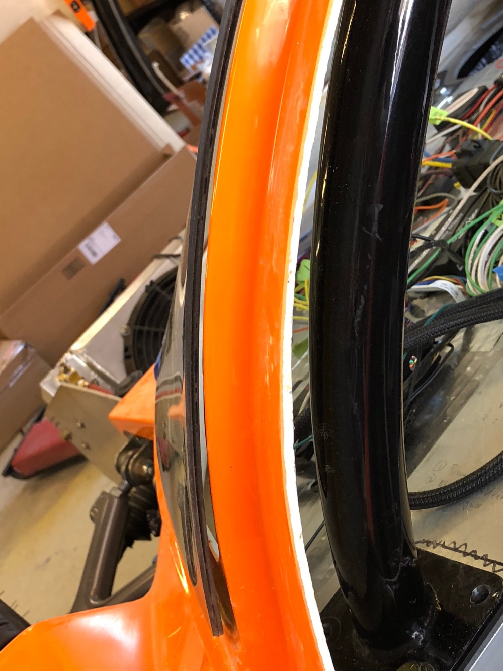
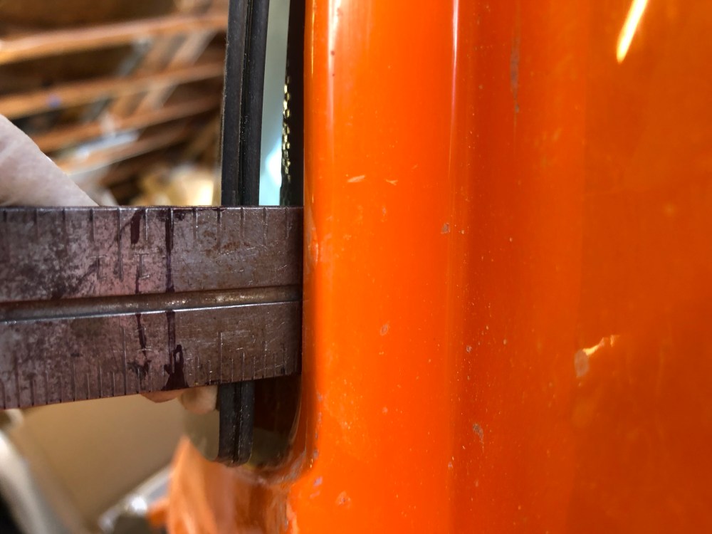
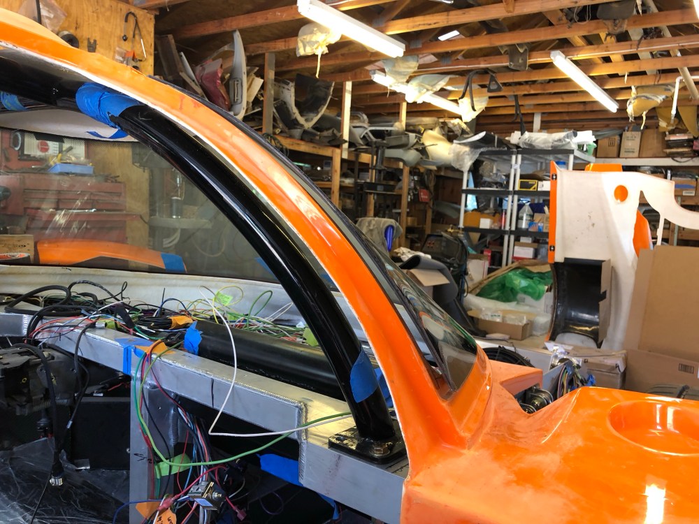
It’s once again time to put my big boy pants on and face the windshield. I had originally traced out a 1″ flange to support the windshield but if you read the manual, it recommends a 3/4″ flange at most, with 1/2″ being the smallest recommended flange.

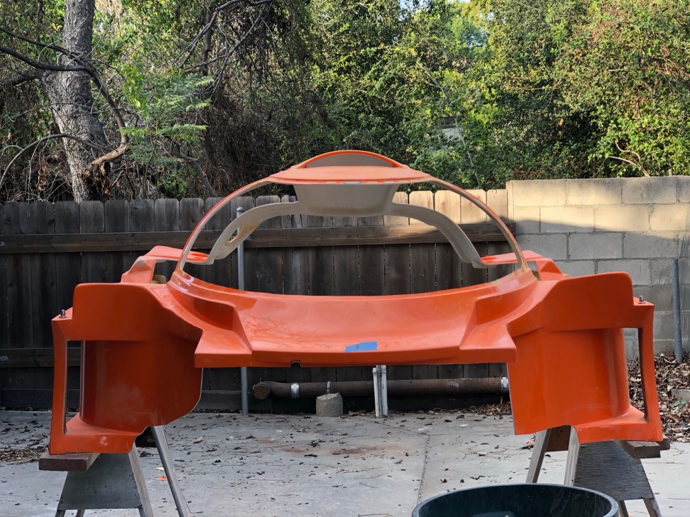
Windshield fitted! And it doesn’t fit.
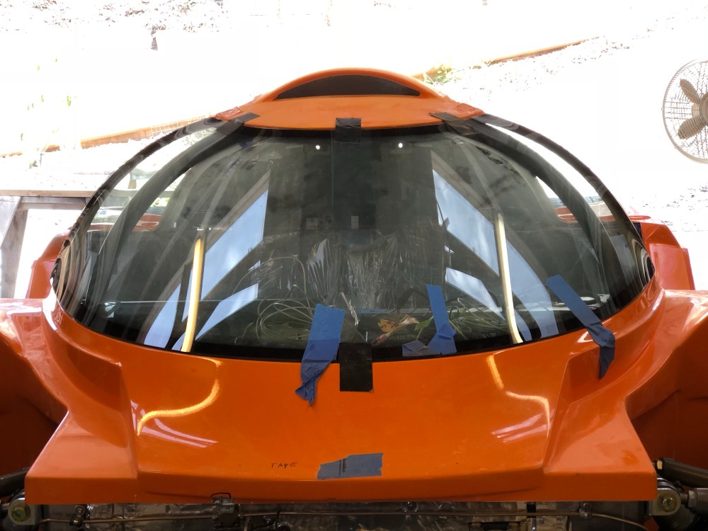


It’s been a recurring theme in many build threads, the windshield never really fits right off the bat. Most builders I’ve spoken with have really struggled (or are still struggling) with this portion of their build. With that nugget of knowledge in hand I was fully expecting my experience to be no different. I suppose expecting that I would struggle with this makes this less of a bitter pill to swallow.
Based on as much reading as I’ve been able to find on the topic, it seems AJ’s build thread, post #86, is the definitive how-to on installing the windshield. In it, he uses a spreader to spread the bodywork apart, widening it enough to meet with the windshield. Once he was able to get the windshield to drop in nicely he locked the bodywork in place. I am not feeling so lucky.
I tried to spread the bodywork but it was taking an intense amount of force to get it to budge at all. I was super freaked out and expecting to hear a CRACK as the bodywork imploded on itself. After messing around with the bodywork for some time I took a different approach.
I did exactly what you’re not supposed to do.
It seems if you push in on the windshield the two sides appear to be independent of each other – push in on the passenger side and it doesn’t affect what’s going on at the driver’s side and vice-versa. With a small amount of pressure I was able to get the driver side to push in almost flush. On the passenger side, I was able to get it down to about 1/4″ with a moderate amount of pressure. I have no idea if that amount of pressure is going to cause the windshield to crack but I’m going to go down this path rather than risk really screwing up my bodywork. If I crack the windshield (and I’ve heard of this happening to multiple people) at least that’ll be less painful to replace than the spider. I’ll use windshield urethane to fill in whatever gaps are left – I don’t plan on putting so much pressure that it’ll be a flush fit all around. So between the tweakage of the windshield and some more trimming of the flanges, I think we’ll get the windshield to a halfway decent place.
As it is, the windshield already looks a bit wonky to me, so having it protrude a bit at the edges is an acceptable “bleh” on the build, one I’m willing to live with.
See? I CAN keep my OCD in check!
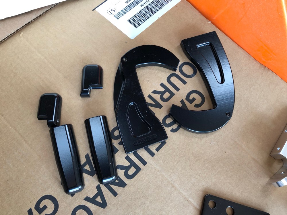
While the body was in the midst of being hacked up I worked on rough fitting my doors. I’ve diverged from the build manual in terms of how the hinge/door are actuated. The SLC uses a J-shaped hinging mechanism. It allows the door to rotate out and upward at the same time – much like the Ferrari Enzo did.

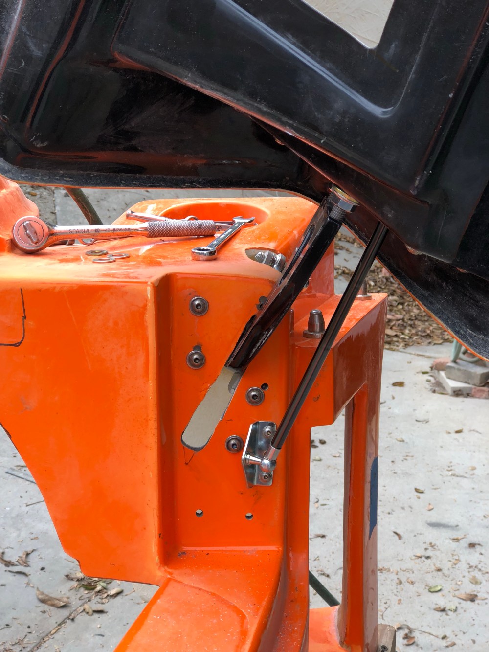
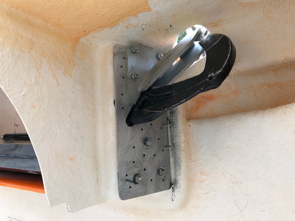
The RCR standard build configuration incorporates a gas strut that is attached to the J-hinge and pushes up on the hinge to assist in door opening. The issue is that the attachment point is such that the hinge can only travel so far before the gas strut is fully extended and the hinge is no longer able to rotate outward. This creates a door opening angle of about 60-degrees, give or take.

Enter the “Mini Mesa Mod” – it’s something Allan mentioned in his #17 build. Instead of attached the gas strut to the hinge, the strut is instead attached to the inner door and anchored to the forward jam location. Moving the strut to this location allows the J-mechanism to articulate further, giving you a greater degree of door rotation. A huge thanks to Allan for giving me a hand with this particular modification. I’m not sure what Mesa’s actual modification was but thanks to Mesa for the initial concept!

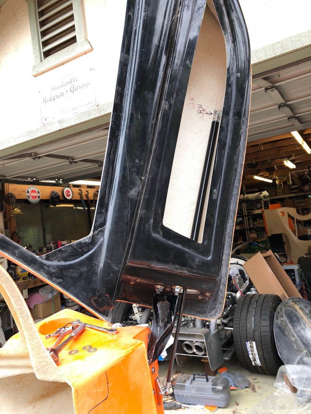
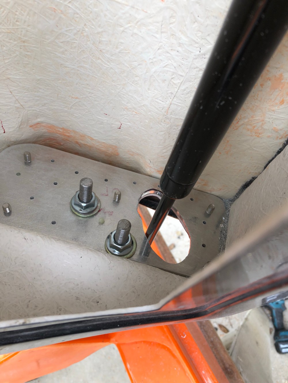
The following is a short video shot from the perspective of the opening in the door skin, looking down at the strut pass-thru. This gives you an idea for the arc the strut travels through as the door articulates.
Parts needed for the Mini Mesa Mod, available from McMaster:
- Gas strut PN 9416K22, 2 req’d
- Fittings for gas struts PN 9416K79, 4 req’d
- Ball stud mounting backet PN 9512K92, 4 req’d
The gas strut has a total length of 28″ and is charged to produce 50 lbs of force. With this part number, the door is able to easily be lifted and closed without undue force. When determining anchor locations, I held the door in the fully open position and located the anchor points such that the strut would need to compress approximately 1″ in order to mount onto the anchor points. If the anchor points are set such that the strut is fully extended when the door is fully open, there’s not enough strut assistance.
On opening, a slight push to get the door started and it’ll go up on its own. To close, light pressure is needed to bring the door down. Note that the door is currently in its lightest possible state – no window installed, no lock mechanism, no handles, etc. I expect with another few pounds of mass added to the door it may take some light effort to bring the door to fully open instead of it opening on its own. I plan to add a good amount of sound and heat shielding to the door so we’ll see if a higher pressure strut or an adjustment of the anchor points is required. Note that I will not be using the optional door skins.

One Comment Add yours