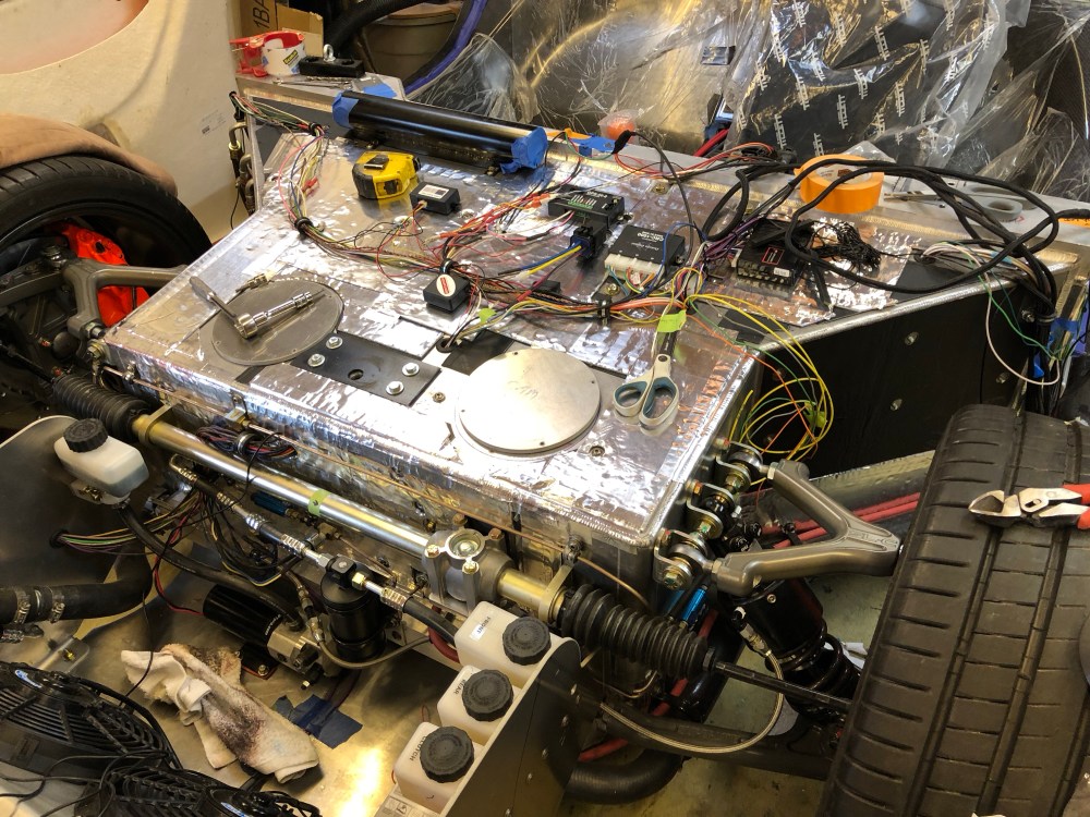
Sometimes it seems like it’s one step forward, two steps back with this project (Okay, a LOT of times). As I’m approaching the last few turns and headed for the finish line, it’s time to start closing out the interior. Most everything is at 80-90% now and I’ve mounted just about everything that needs to be mounted and run just about all the wiring.
It seems many builders apply sound damping as Step 1 of their builds. I’ve sprinkled it on throughout my build in areas where I’m fairly confident I won’t be making any more changes. The concern with applying sound damping too early is if you need to come back and drill holes through the material, it really gums up your drill bits. Have to cut a big hole? Ouch … can’t imagine how nasty your hole cutter is going to get. So I’ve delayed adding sound damping to the interior as much as possible since there are so many wires/hoses that pass through the passenger compartment.
Now that just about everything is mounted and positioned it’s time to take it all apart so I can add sound damping – one step forward, two steps back.


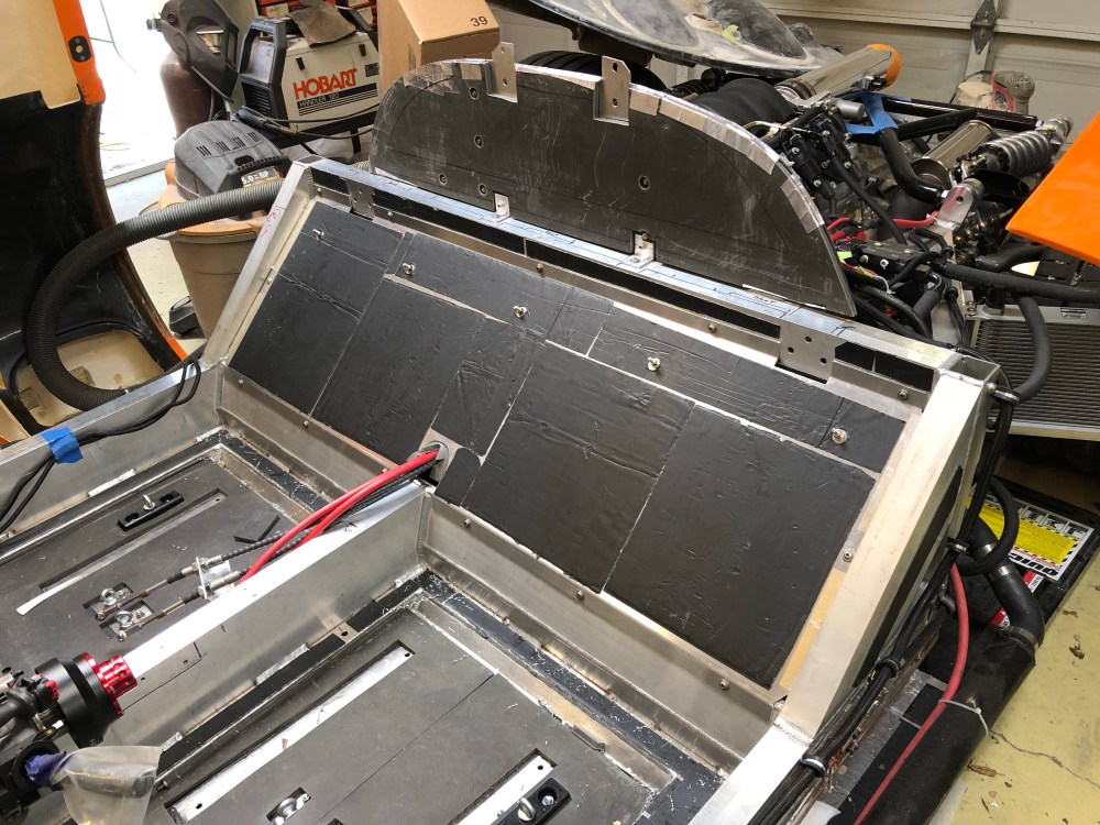
Yeah, I’m going to some pretty extreme measures to try and keep heat out of the passenger compartment. I have a similar configuration for just about every surface in the passenger box. For those keeping track, here’s what I’ve got:
Exterior heat source/exterior ==> Thermal Block ==> Damplifier Pro ==> Aluminum panel ==> Damplifier Pro ==> Luxury Liner Pro ==> Heat Wave Pro ==> Some sort of carpet or interior finishing piece/tub ==> interior space
That’s a LOT of layers. And it comes at a pretty decent penalty in terms of weight. I’m going to throw out a guess and say I’ll have one of the heaviest SLCs on the road by the time I’m done. However, since this is a road car, driver comfort, NVH and BSR reduction are critical for me. I would guess I’m throwing on an additional 100-150 lbs of noise and thermal protection compared to the typical SLC – which typically only has a single layer of sound damping and a thin sheet of Reflect-a-Gold heat shielding.

So there’s a lot of reasons for holding off on adding sound damping and thermal shielding until very near the end of the build, as frustrating as it may be.
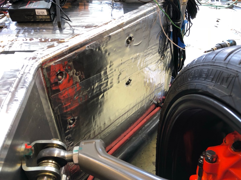
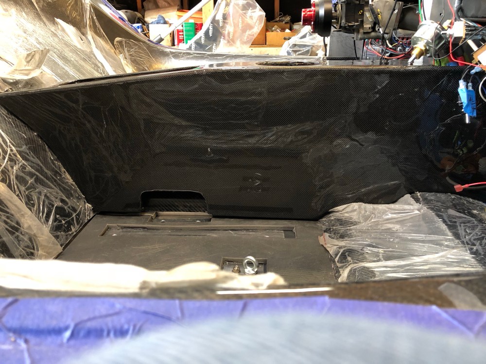
This next part is a case of one step back, two steps forward! Recall the fuel tank closeout panel that I had finished earlier? I didn’t final install it because I wasn’t sure how I was going to sound/heat treat the passenger side compartment of this panel. With the tub rough fitted into place, I was able to determine that there’s *just* enough room to slip a sheet of Luxury Liner Pro in between the tub and the closeout panel – SWEET!
I pulled the panel back off and swapped the 5x bolts passing through the panel for a longer set. On the fuel tank side of this panel I’m running a sheet of Luxury Liner Pro and a layer of Damplifier sound damper. On the passenger side, I’m running the same – another layer of Damplifier sound damper and a sheet of Luxury Liner Pro (I’ve been strategically using the Damplifier Pro as I’ve been running low, though I have a ton of the standard Damplifier from my B-stock box). The 5x bolts passing through the plate are used to secure the Luxury Liner Pro sheets in place in addition to spray adhesive. I don’t have great confidence the spray adhesive will hold up over time so these fasteners are my belt and suspenders solution.

If that doesn’t stop heat and engine noise from getting in via the fuel compartment I don’t know what will!
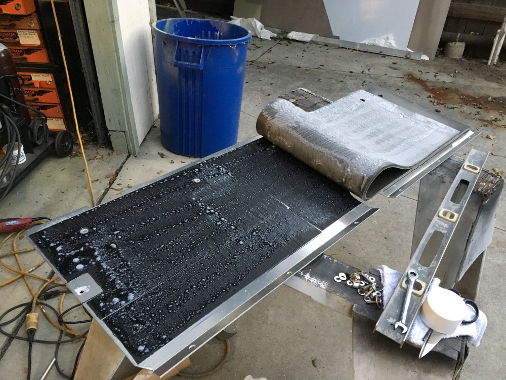
Things didn’t stop at the closeout panel – I also added another layer of Damplifier to the back of the tub. I had consumed about all the room there was between the tub and fuel tank closeout so there’s a few patches where I elected to not apply the sound damper.


This is very exciting – with the upgrade to paying status, I’m now able to post videos to the blog! Below is a short video showing the difference made by adding just one sheet of Damplifier to the tub (you can see a corner of it in the upper left of the video). The first few taps were made with the handle of my scissors. The later taps were made using my knuckles. There’s a very distinct and noticeable change in the sound coming from the tub. I have an RTA app on my phone so the sound engineers out there can maybe explain what it is I’m seeing. It appears peak SPL at ~2k+ seems to be reduced with the addition of the sound damper. I think this makes sense to me, this type of damper is only good for knocking down the high frequency stuff, there’s not enough mass to do much with the lower frequency stuff (which is where the Luxury Liner Pro comes in!). However, it seems maximum decibels measured is about the same between the two. Again, I think this makes sense – the Damplifier is just too thin to absorb much energy, which is again, where the LLP comes in.
This ad hoc demonstration really seals the deal for me – I’m glad I invested the time and money into incorporating the LLP into my build. Adding sound damping helps reduce ringing/high frequency noise, but does very little else to quiet the cabin. Something like LLP is really needed to add a ton more mass to knock down the low frequency sound and absorb/block noise before entering the cabin.
Center console:
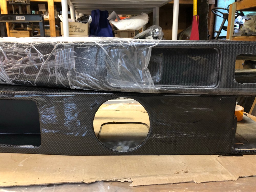
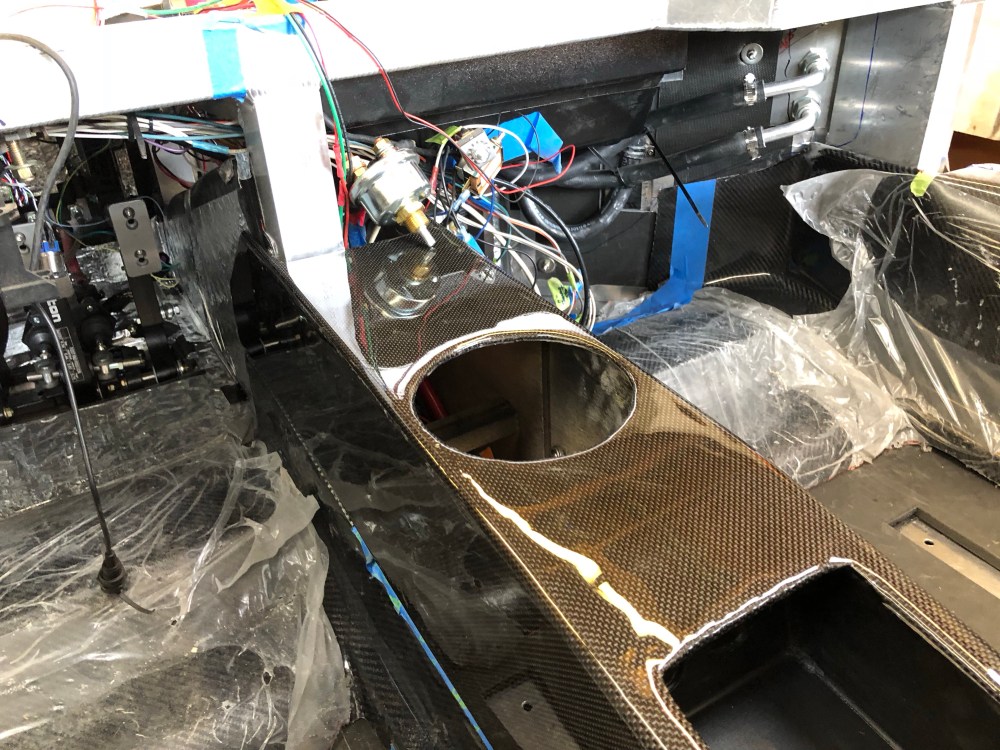
Unfortunately that really nice carbon fiber center console that was included as part of the carbon tub is not compatible with the Audi R8 shifter mechanism. The shift gate is too wide to fit within the narrower RCR center console.
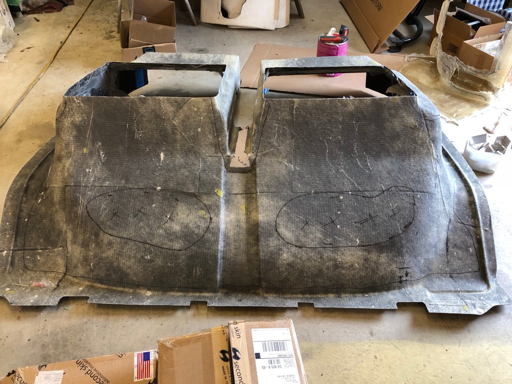
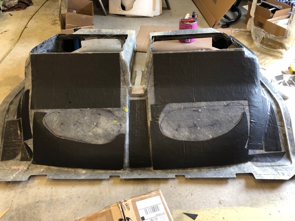
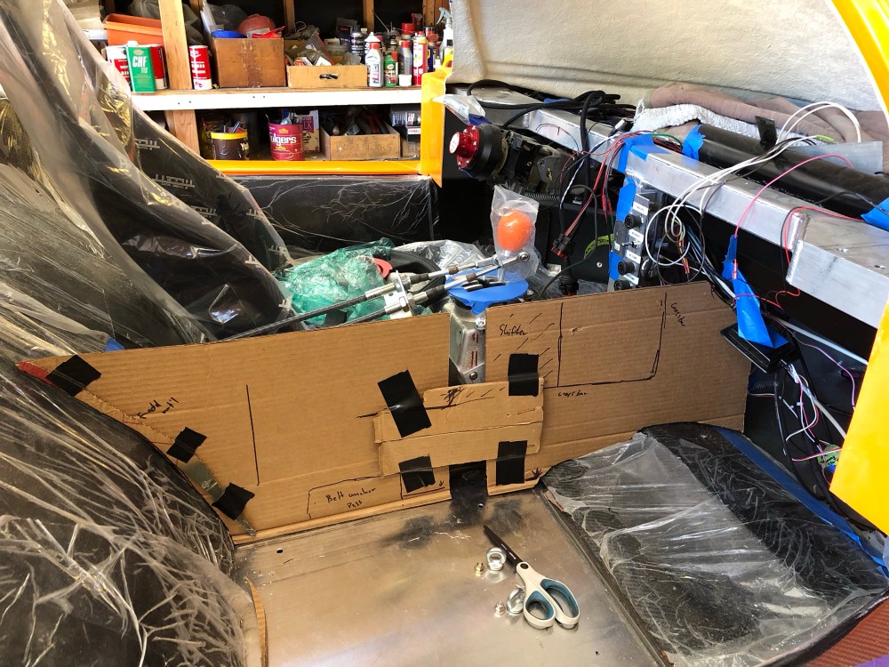
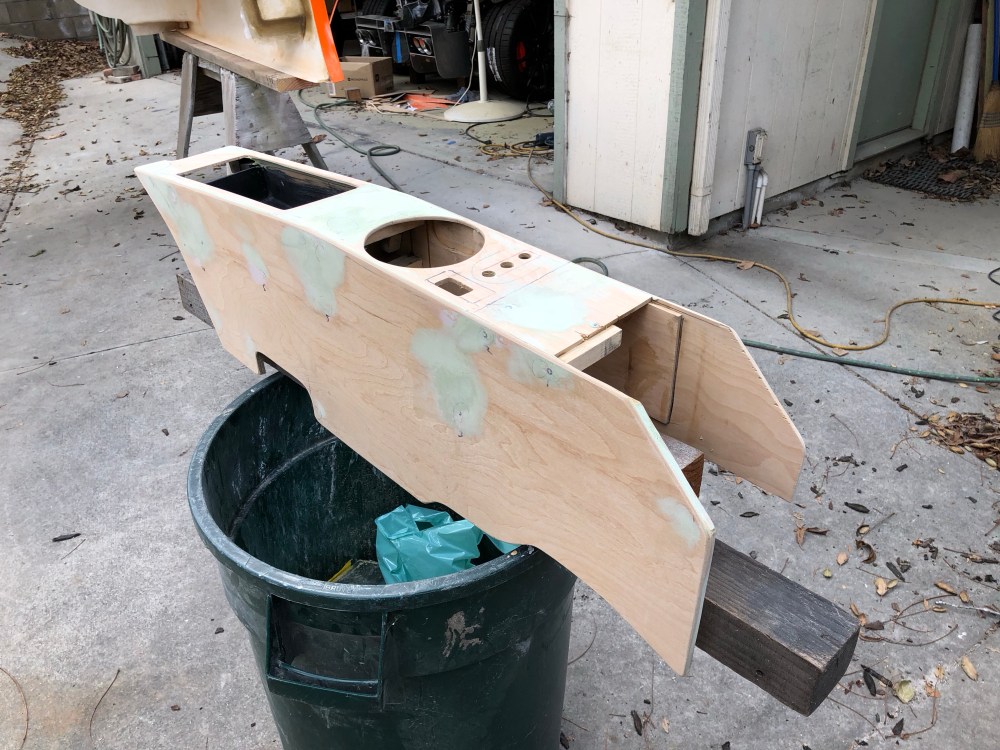
I’ve always wondered how custom center consoles are made; I watched a bunch of YouTube videos and chatted with Bob to get an idea of how to construct one from scratch for the SLC. I decided to start by roughing out a general shape using cardboard to make a template, then replicating it using wood. The console is actually made up of 2 sheets of 1/4″ wood as there are reliefs cut out of the interior panels to make room for the large shifter mechanism.
With the rough shape completed and button locations mapped out, I wasn’t quite sure what to do next. I had originally intended to have a local upholstery shop do a fabric cover but after discussing with Bob it seemed this might not be the timeliest option. If I want to get this car on the road sooner I would have to do the finish work myself. Having zero knowledge of (and a lack of desire to learn) how to upholster, the next option seemed pretty logical – cover it in carbon fiber!
Carbon fiber skinning: Skinning a part in carbon fiber is a relatively low tech, resource intensive/wasteful process – but it’s low skill and can still produce a beautiful part once complete. In fact, I think skinning produces a more visually appealing product than one that was vacuum formed. Much of what I love about carbon is the aesthetics – as light hits the carbon weave it reflects off the individual threads and you can produce a really rich, glossy part with a ton of depth due to the curvature of the carbon strands. Using vacuum to set the carbon generally means the weave will become compressed, decreasing the amount of curvature of each strand. This gives the carbon a much more “flattened” aesthetic. When a part is skinned in carbon, the weave is allowed to retain more of its shape as the strands criss-cross – which in turn produces a part with more depth.
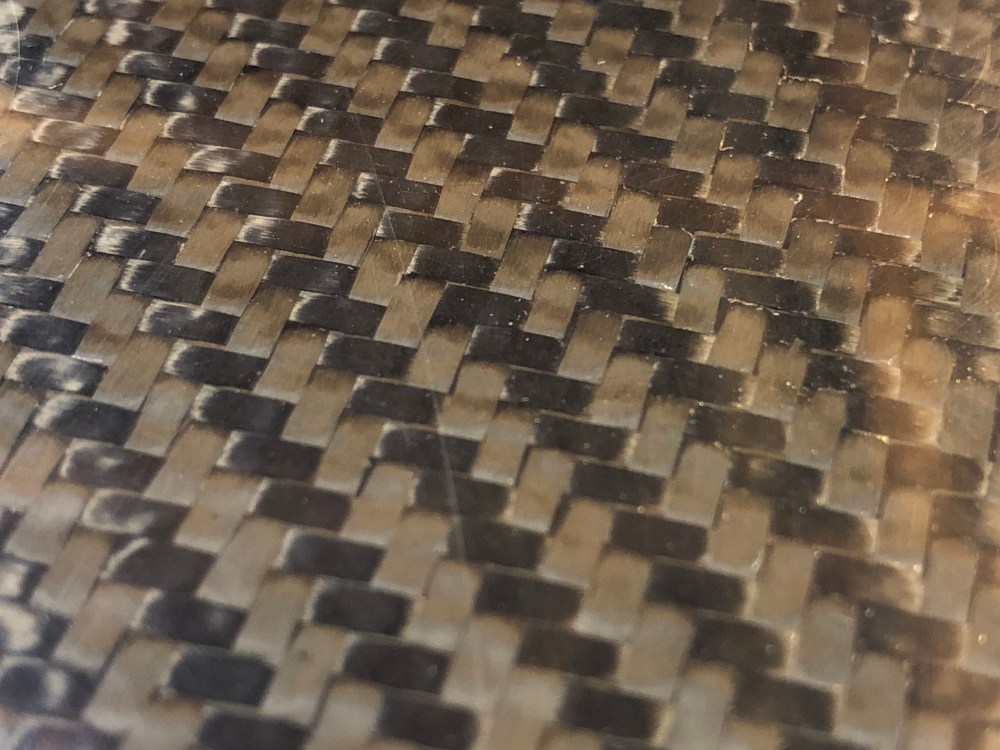
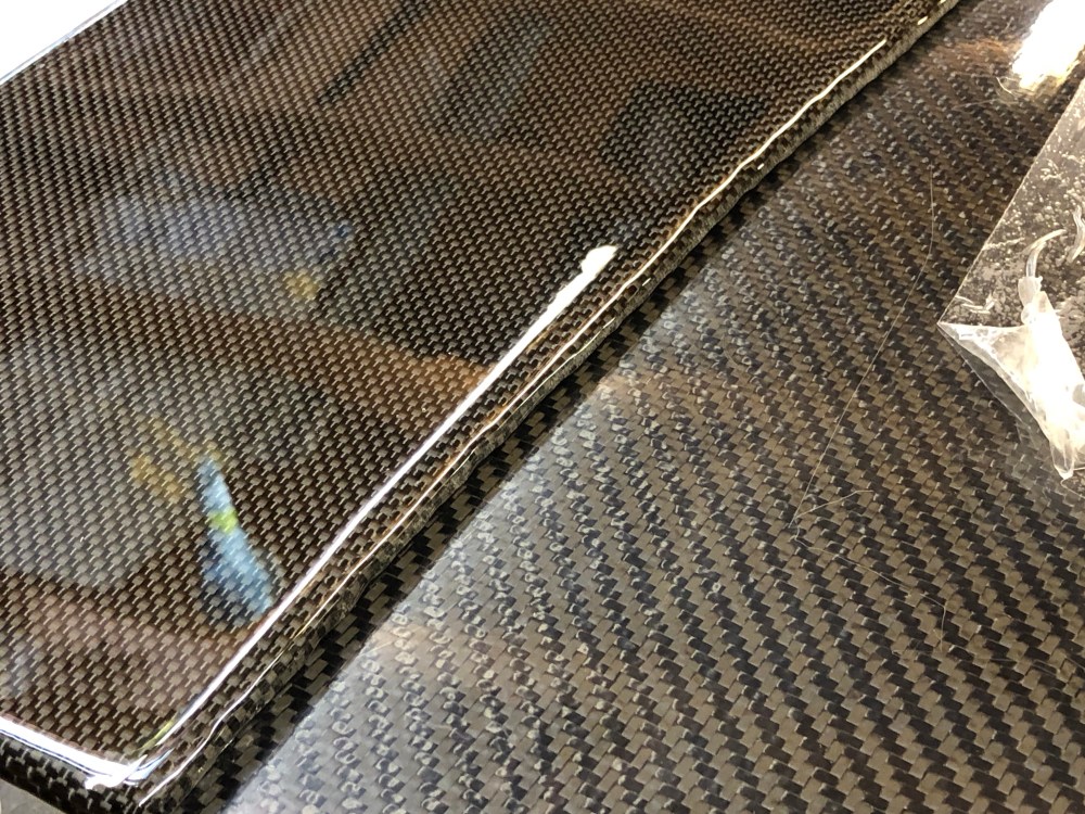
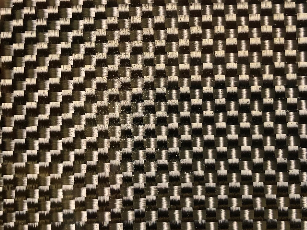
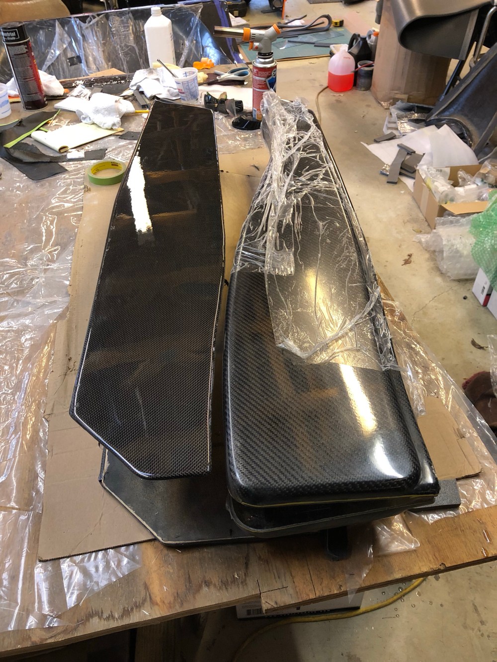
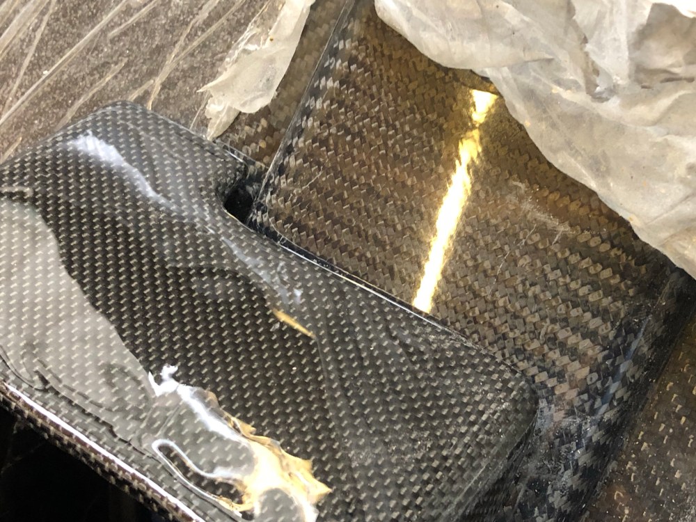
Here’s a comparison between the factory vacuum formed 2×2 twill vs the plain weave I used on my console:


If we’re all being honest, I don’t think anyone purchased the carbon option for weight savings/higher performance (unless you’re talking about the rear wing). Most of the RCR carbon pieces appear to be 1-2 layers of carbon backed by fiberglass anyway. I have an obsession when it comes to carbon fiber – my wife knows I’m thinking about carbon fiber because she says I get a far off look in my eyes, I start foaming at the mouth, and I whisper “car-bone” … “car-bone” … under my breath like it’s some kind of mantra. So skinning parts may not be the “best” way to produce a part, but it’s the best way to produce the “nicest looking” part at the expense of more waste and more weight.
When skinning carbon fiber, it doesn’t like bending over sharp corners so I sanded and bondo’d everything till it was relatively smooth and there weren’t any sharp transitions. I had been using 1+ year old bondo body filler and struggled to get it on before it set up on me. It was getting to be a real bear to work with the stuff. Bob recommended I give Evercoat Rage Gold a shot – the stuff mixes and lays much easier than the Bondo did. Maybe it was the age or maybe the Evercoat is just better – I don’t know, but switching to the Evercoat made it a much more enjoyable process!
Pro tip: if you’ve got a really old can of bondo/epoxy/resin/whatever and you’re struggling with it? Toss it and get a fresh can. Your time and frustrations are worth more than the few bucks you’re saving by trying to use up some potentially expired stuff.


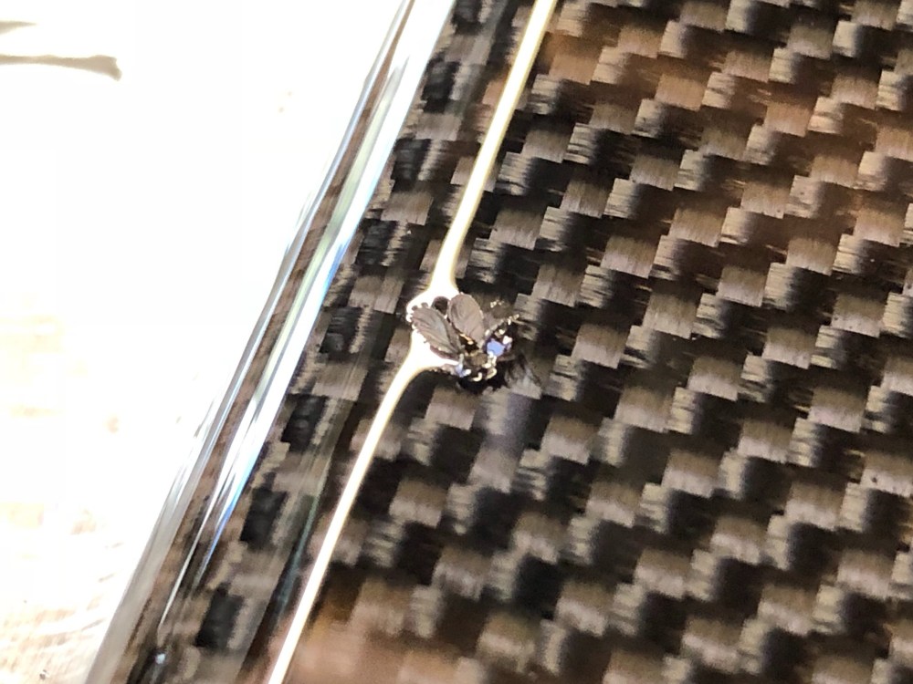
For the center console, I used 5.7 oz/sq yd plain weave carbon cloth. A 3k 2×2 twill weave will conform easier, but the bends and contours on the center console aren’t very extreme and the plain weave had no issues moving as necessary to get great coverage without gapping or pulling oddly.
I generally prefer the 3k 2×2 twill look but this weave has a very defined pattern to it and I didn’t think I would like how it changed going from the horizontal to vertical panels. The plain weave has a much more subtle pattern and is finer – I was very pleasantly surprised by how nice it looks despite being folded over and stretched. The plain weave creates that angled pattern in both directions, depending on how you’re looking at the weave and how the light hits it.
I elected to use West System’s 105/207 epoxy combination because the 207 is their most optically clear epoxy hardener. The 205/206 hardeners will have a yellowish tint once cured. Additionally, the 105/207 combination contains UV inhibitors to help protect the epoxy from yellowing over time due to UV exposure. Regardless, it’s recommended to use an automotive clear coat over the finished piece for added UV protection.
The West Systems 207 hardener has a 20-30 minute (usable) pot life in warm weather; I found even at the cooler temperatures (~55-60F) pot life was shorter than I’d expect. Part of the issue may be that I’ve been trying to get rid of all the air bubbles by hitting the epoxy with either a heat gun or butane torch – the torch works really well for knocking out surface and near-surface bubbles whereas the heat gun seems to work better for making the epoxy run more, or decreasing its viscosity. This additional heating via the torch or heat gun may be decreasing my pot life. My general order of operations when mixing up the epoxy:
- Mix for ~2-3 minutes to ensure the hardener is fully mixed.
- Let sit for 8-10 minutes to allow bubbles to form and rise to the surface.
- Hit mixture with torch to pop bubbles.
- Gently swirl the container to help bring more bubbles to the surface.
- Hit mixture with torch.
- Apply epoxy.
I’ve tried letting the pot sit for longer than 12 minutes but it seems after this time I would get localized gelling which makes application more difficult. If anyone’s got any tips on how to use this stuff I’d be mighty appreciative!
It seems even with the above routine I’m still generating micro-bubbles. I’m not sure if the bubbles were present when I applied the epoxy, or if they formed after the epoxy was applied.

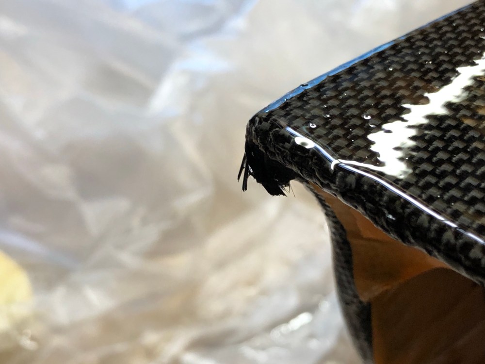
CAUTION: When using a butane torch to pop bubbles, it will generate a LOT of heat – enough to scorch and cause the resin and carbon fiber to become permanently damaged. During one of my test pieces I let the torch sit just a bit too long and the resin started bubbling – almost foaming – and the carbon cloth started going up in smoke. Bad for your lungs (you should be wearing a very good respirator whenever working with this stuff!) and bad for your part.
Unfortunately my hands weren’t moving quickly enough and I managed to singe a portion of my console during the wet out coats. A total bummer but I was too far along to scrap it all now. It’s not noticeable unless your nose is pressed up against the console but I’ll know it’s there.
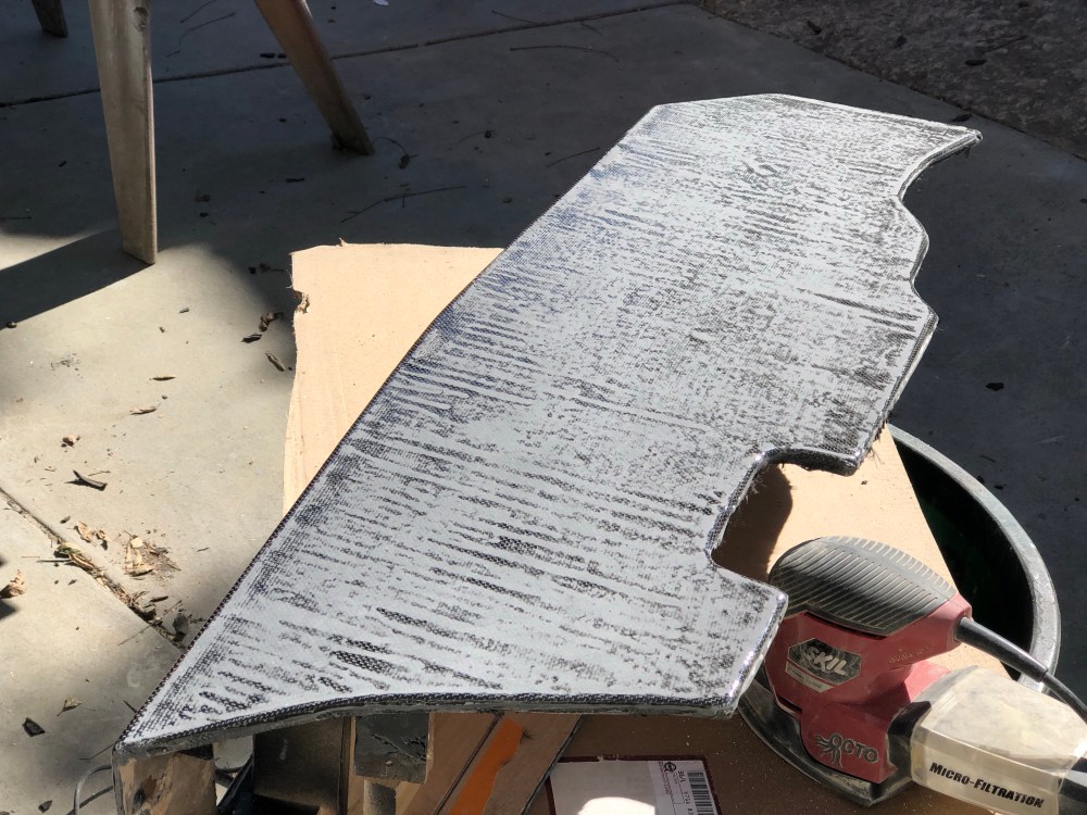
After the initial wet out coats are fully cured, any high spots, defects, etc are sanded down to even out the epoxy coating. It’s critical that all epoxy surfaces are sanded before proceeding with the final build up coats otherwise adhesion problems may occur. It’s also critical that any debris generated from sanding is removed otherwise it’ll get locked in and these defects will be visually apparent.
The squeamish should stop here, what follows next is what happens when you sand a perfectly good piece of carbon fiber …
.
.
.
.
You were warned!


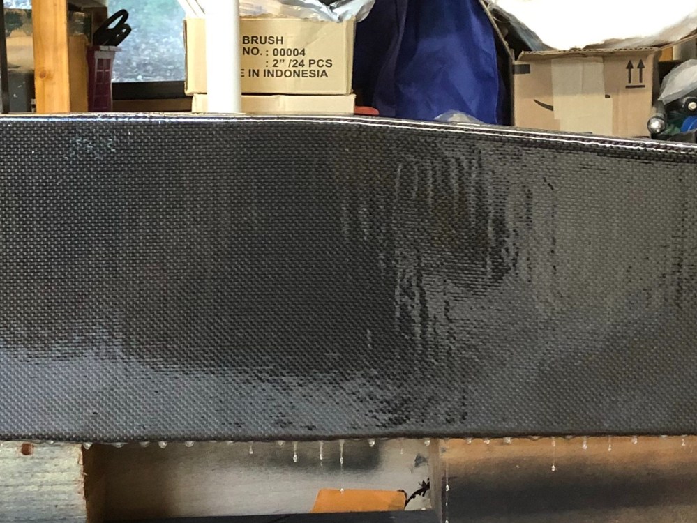
Knowing that I was going to once again have issues with streaking runs and drip formations, I decided to break up my final coats into 3 “sessions”. Since my console essentially consists of 3 flat panels, I felt the best solution would be to coat each side one at a time, placing the side to be coated up, and not apply any resin to the other surfaces. This isn’t the most time-efficient process for producing a part since it requires about a full day for each panel to cure before moving onto the next. However, my initial results with brushing the epoxy on clued me in on how to better handle these large vertical panels.
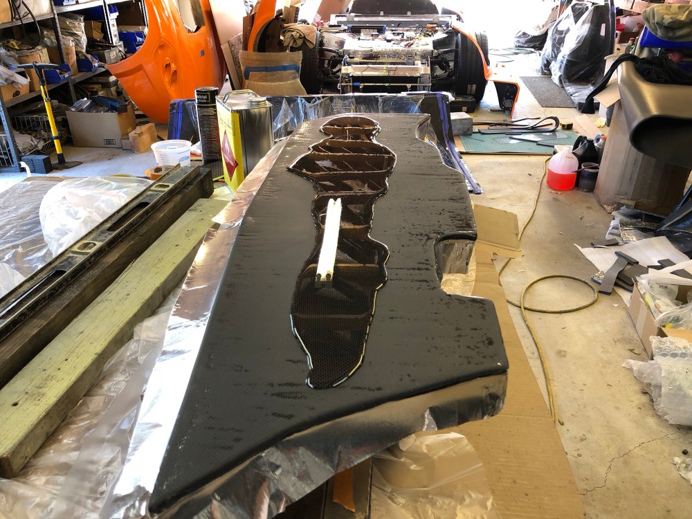
Luckily I had added enough resin where I had buggered things up that I’m confident I can produce a flat surface without having to sand too much back.
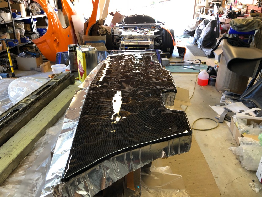
After the first panel cured enough so I could handle the part, I removed the masking and started working on the driver side.

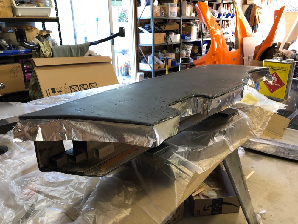
Another day, another cured panel. On to the last one. This is the most critical panel as it’s the one that I’ll be staring at every time I’m in the car. This last panel was a bit more challenging because it’s actually 2 planes joined together, just aft of where the shifter gate pokes through. During my wet out coats I’d already achieved a fairly thick and consistent layer across the “top” piece so I decided to mount the console so the angled rear portion was “flat”. This will ensure I get a nice level surface across the rear part of the console. Once the new layer is fully cured I can come back and sand both areas flat relative to themselves.


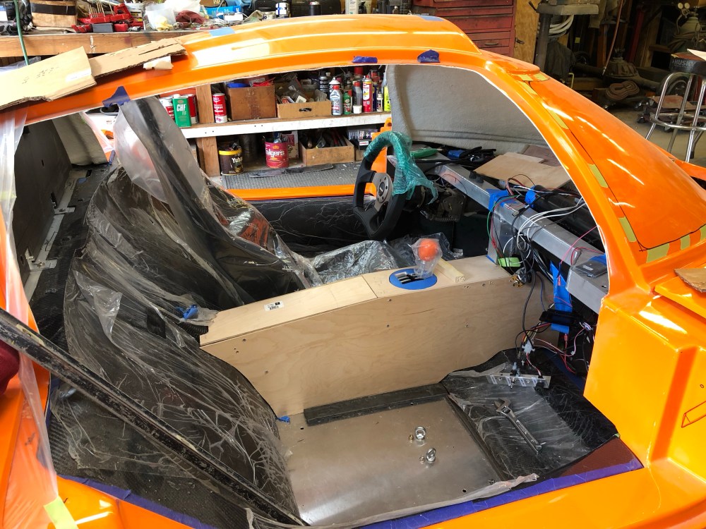
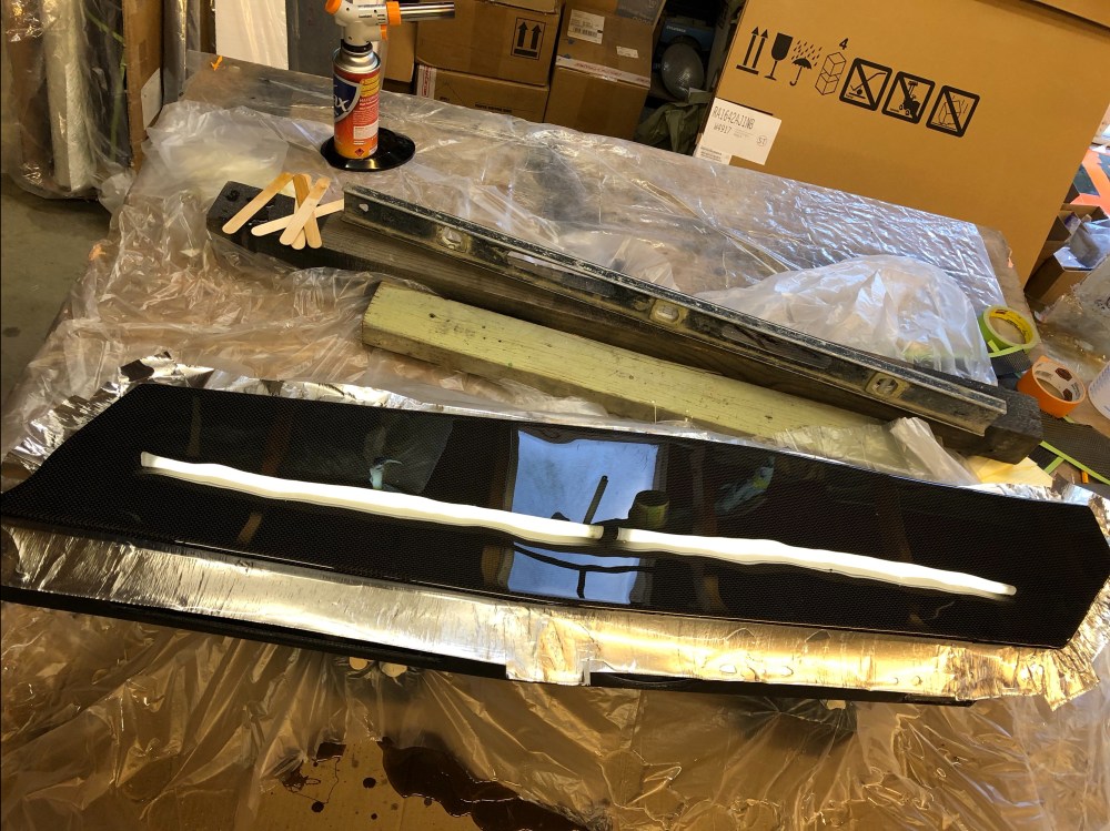
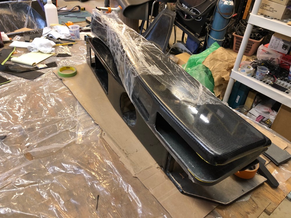
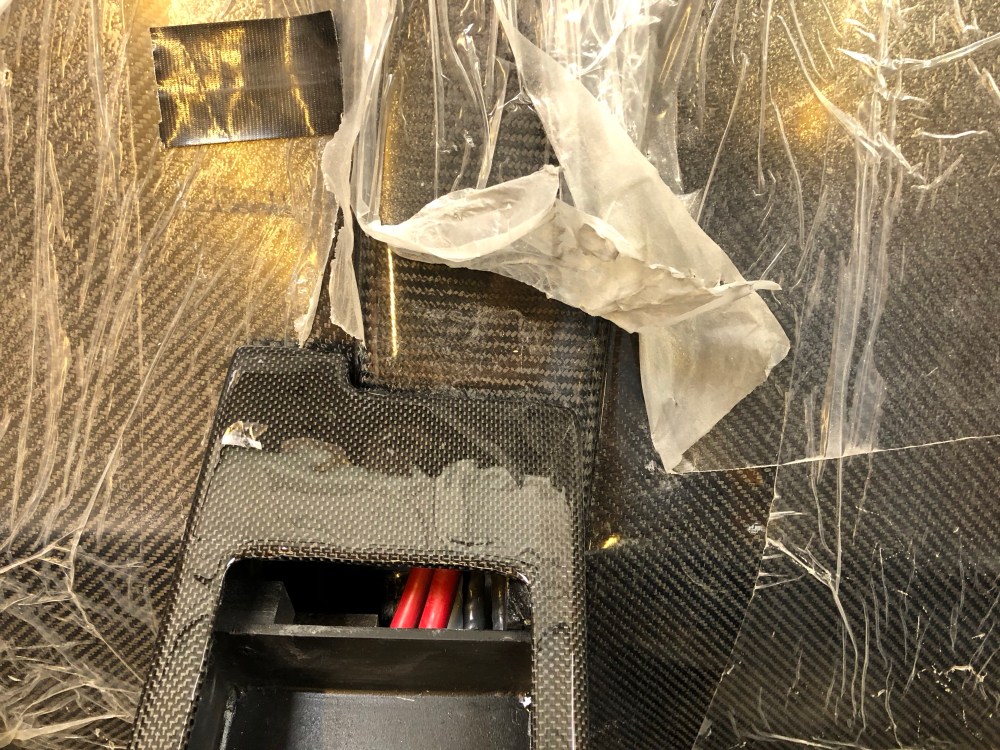
Another day, another cured panel… the last panel! I plan to let the resin continue curing for another few days before sanding it back to get the panels flat. Here’s a few shots showing the rough piece, and compared with the RCR center console to show differences needed to accommodate the R8 shifter mechanism.


I’ll let the console continue curing for a few more days (literature says full cure in 4-7 days) before I start fine tuning and sanding the console. Now that it’s in position I’ve got enough to start laying out my buttons and continue work on the interior.
