Now that the front and rear clams were in decent shape it’s time to turn my attention to the center spider – I’ve always wondered why the center body piece is called the spider. Anyway, it seems like it’s been forever since I started working on fiberglassing and there’s still so much more to go … If the SLC represents one of the better/best bodies available for a component car – what are the others like?!
To be fair, I’ve created much of this work myself as I’m making modifications that I’ve deemed necessary (though I’m sure others would disagree). In fact, this entire post is all about body modifications that aren’t required, go figure. I wonder why it feels like it’s been forever since I started working on the body …
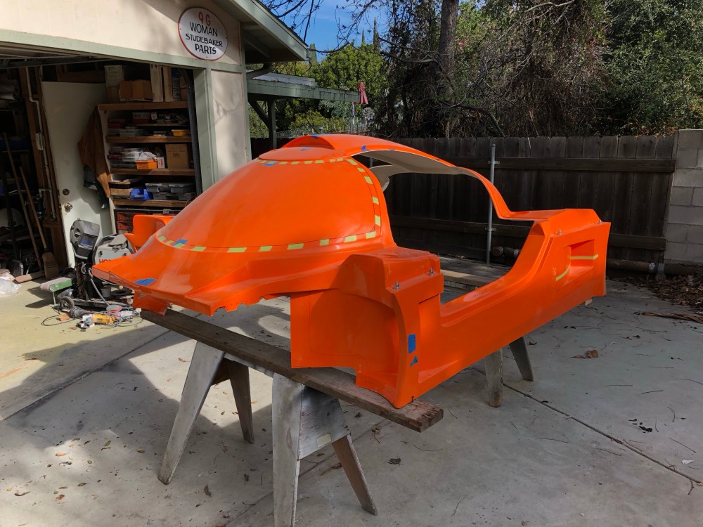
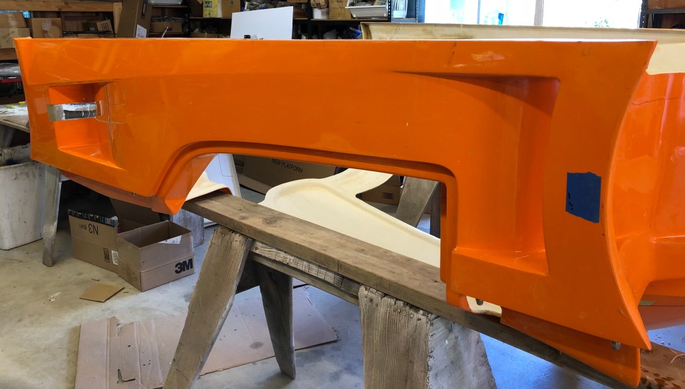
Spider looking all set; ready for some modding!
Wheel well shields [Allan’s mod]:
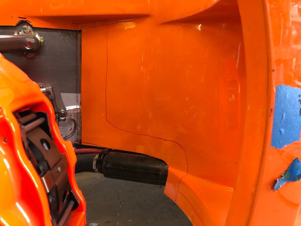
Before we get to the chopping, I need to cover the wheel well shields – see what I did there? Due to how I’ve run my coolant lines up and down the sides of the car, I had to expose the lower rear portions of the front wheel wells. This is a primo spot for dirt/water/debris to wreak havoc; it’s also a great spot for oncoming air to slip underneath the bodywork and create noise while the car is in motion.
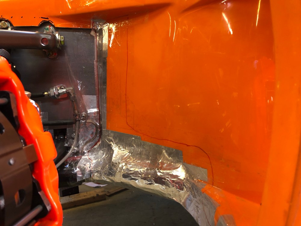
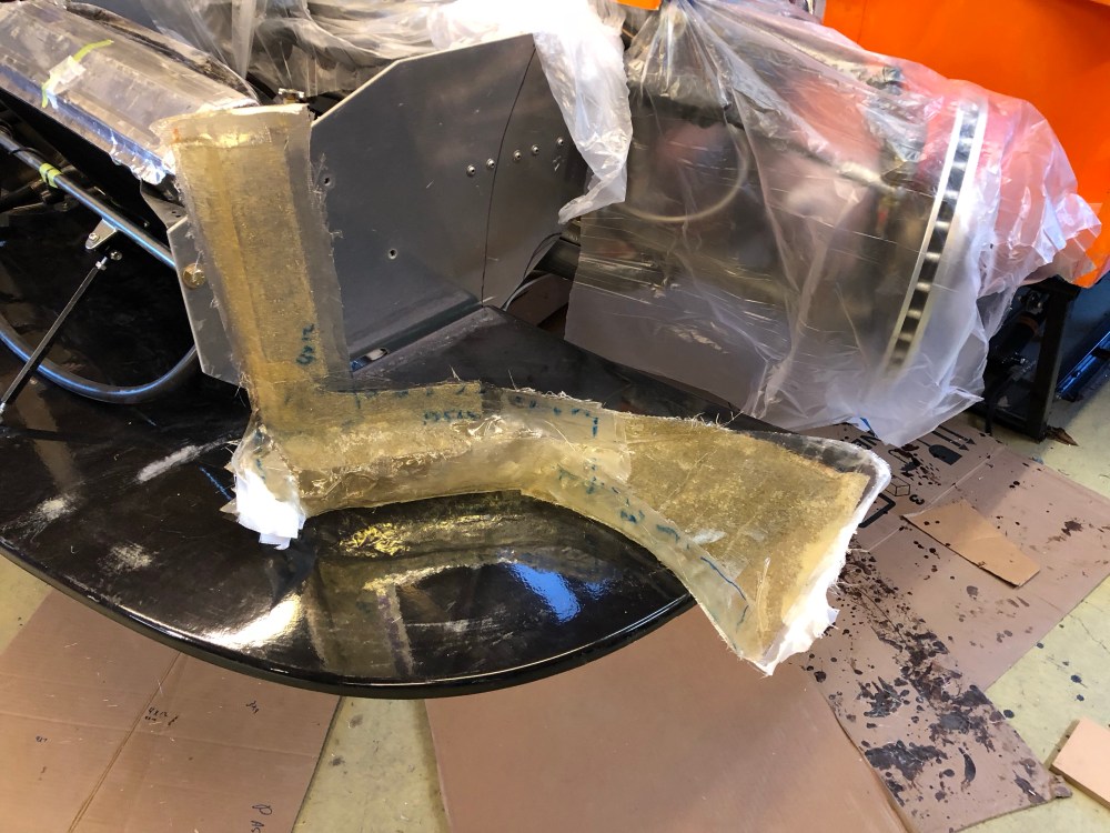
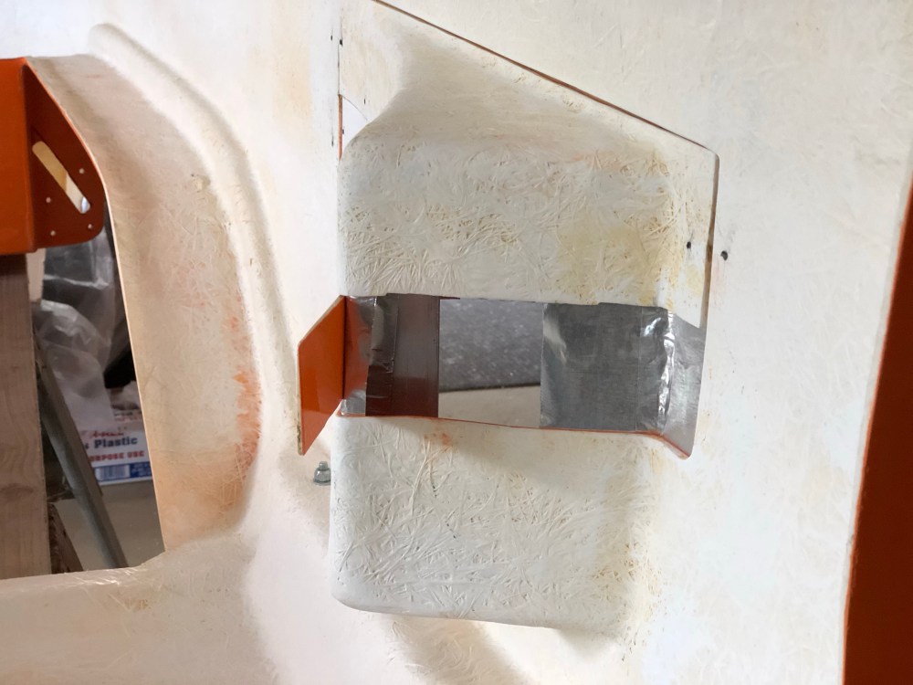
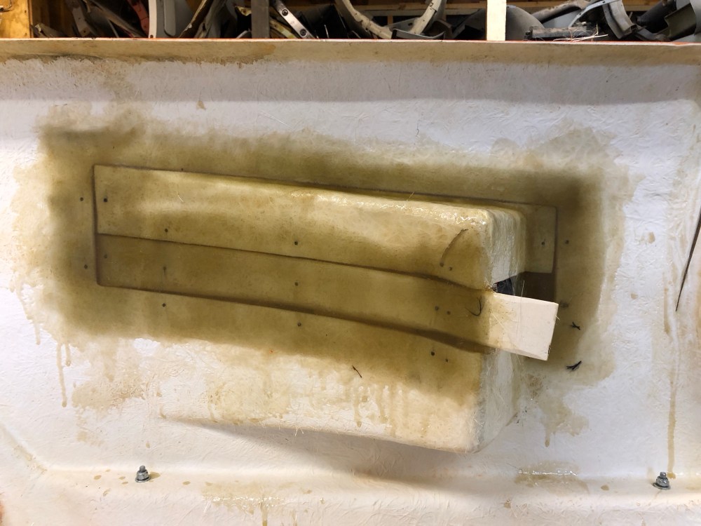
I’m not sure who first came up with these but I’m pretty sure I first saw them on one of Allan’s builds. This shield is non-cosmetic as it will be completely hidden once the wheels are installed. I traced out the approximate area of coverage and used a combination of aluminum tape and packing tape to create the “mold”.
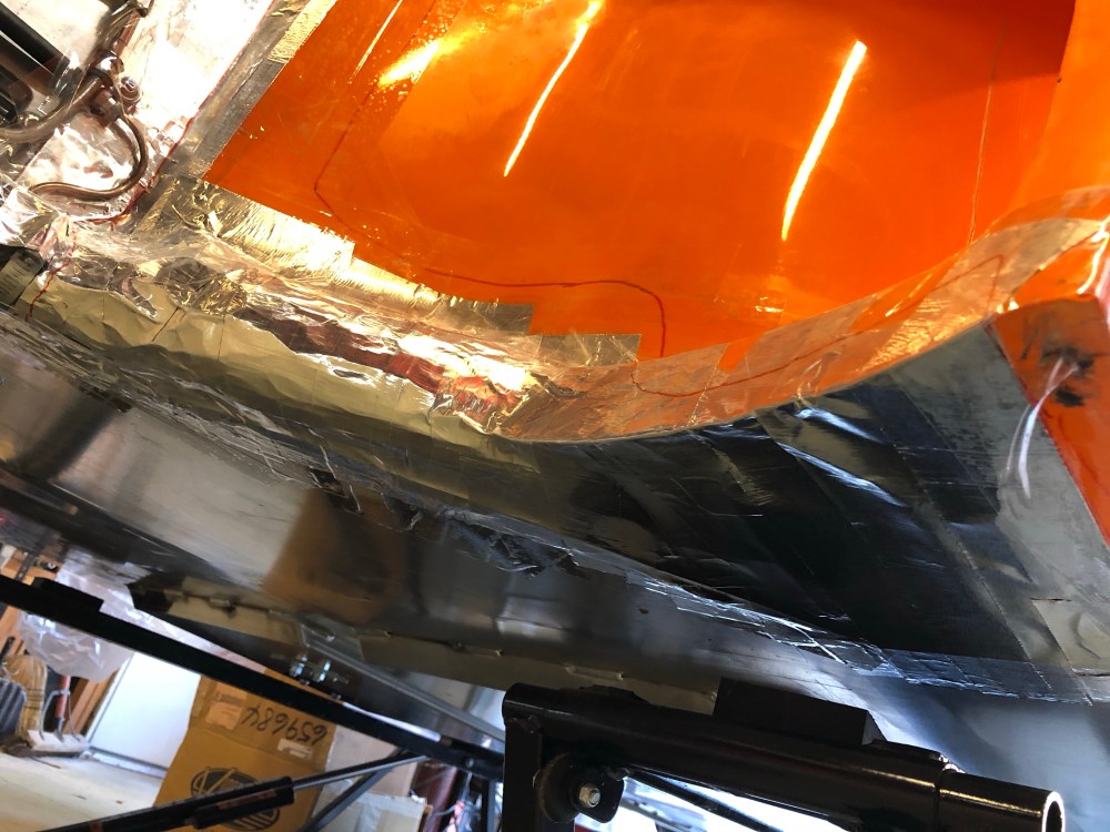
Approximate outline of “shield”.All taped up and ready for fiberglass!I’ve seen shields that only covered a small area of the underside; I believe Allan supplements his shields with a small sheet of aluminum to fully close out the lower opening. I decided to try glassing this whole area in. I’ll be using multiple fasteners to keep this piece in place.Due to the very organic shape of this shield there’s really no other way to make this other than to use something like packing tape for the pattern. I added bits of cardboard to push the tape out and away from stuff to give myself some wiggle room between the shield and what’s underneath. I also strategically used glass mat and cloth to keep the shield flexible where needed and stiff everywhere else. In particular the areas where fasteners will be located and where it contacts the body I’ve doubled up on mat and reinforced resin to give me a strong “edge”.Here’s a shot of one of the shields positioned. Some rubber molding along the interior edge will help keep oncoming air/water/dirt from making its way into the bodywork. Surprisingly, everything was well drafted and there’s not much effort required to push it into place. Better to be lucky than good!
The shields will need more work to make them slightly less than “super ugly” – but not too much since they’ll be hidden once the wheels are installed. Some trimming, a little body filler, and some paint to complete.
Side intake modification [Howard’s mod]:
The SLC has 2 side intakes, 1 located on either side of the body, just aft of the doors. I’ve chosen to locate my oil cooler in the direct path of the driver side intake. I had originally intended to locate my transaxle oil cooler on the passenger side, but have since opted to not install a transaxle cooler. I’ve protected the area for a cooler in case I end up tracking the car more than I think. So for now the passenger side intake will primarily be used for cooling the engine bay.
The factory intake sizing is perfectly adequate for an oil cooler. I happen to plan on building a small duct to ensure all air entering the intake will be forced to flow through the oil cooler – mega cooling efficiency, but may be necessary if I get caught in stop/go traffic for miles on end (an oil cooler fan may be required, TBD).
As adequate as it is, there’s just something not quite right with how it looks. There’s a diagonal feature that runs between the front and rear wheels; the lower edge of the front wheel well vent is created by this diagonal feature. As this line runs from front to back, there’s about a 3″ gap between the lower edge of the side intake and the diagonal feature – it really seems like the lower edge of the side vent should also be formed by this diagonal feature.
Confused? Perhaps some pictures …
Factory bodywork, note the gap between the diagonal line and the side intake, just forward of the rear wheel. The side intake just doesn’t look tall enough …Howard’s car; note how the side intake on his car closely follows the diagonal edge. Both the front wheel vent and the side intake flow together – NICE.
Thanks again to Howard for the inspiration behind this mod and for his detailed how-to located in his build thread.
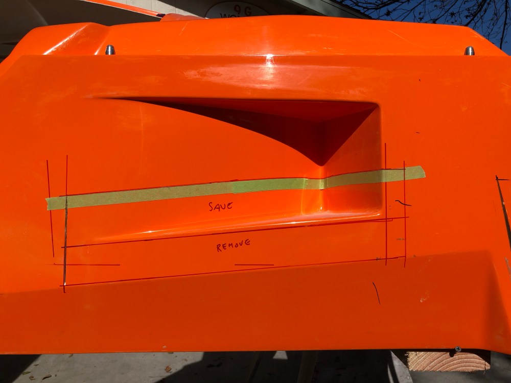
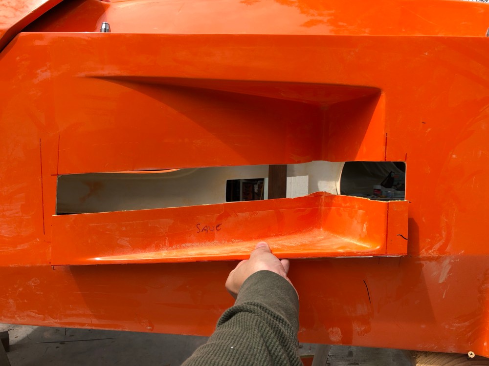
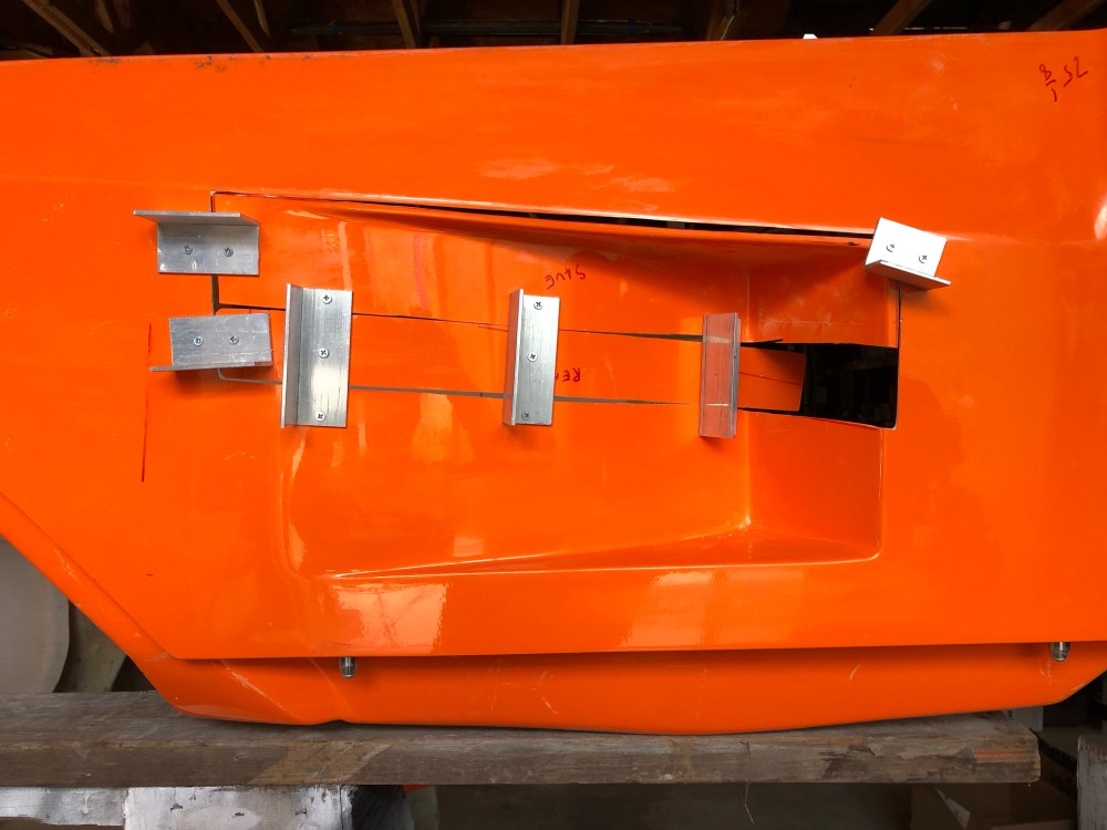
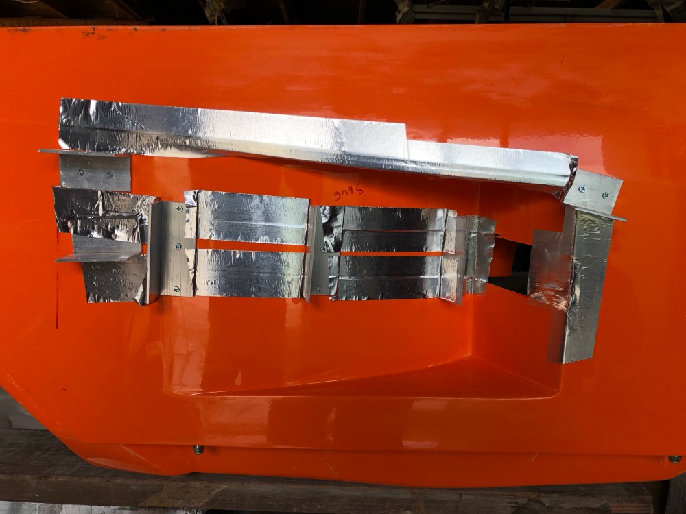
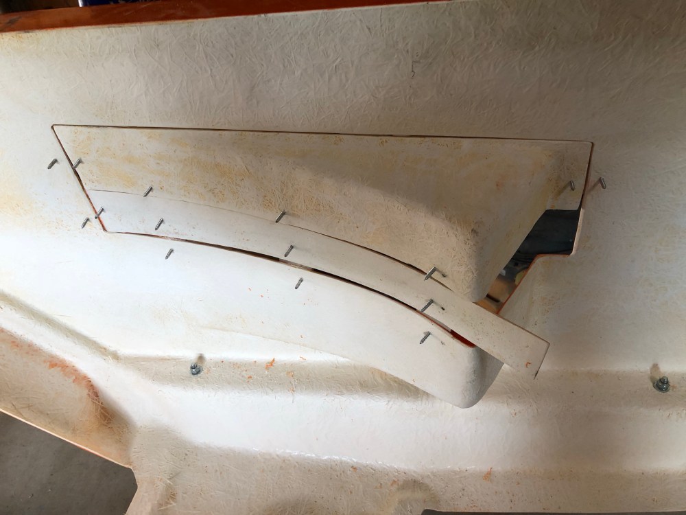
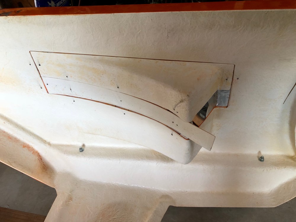
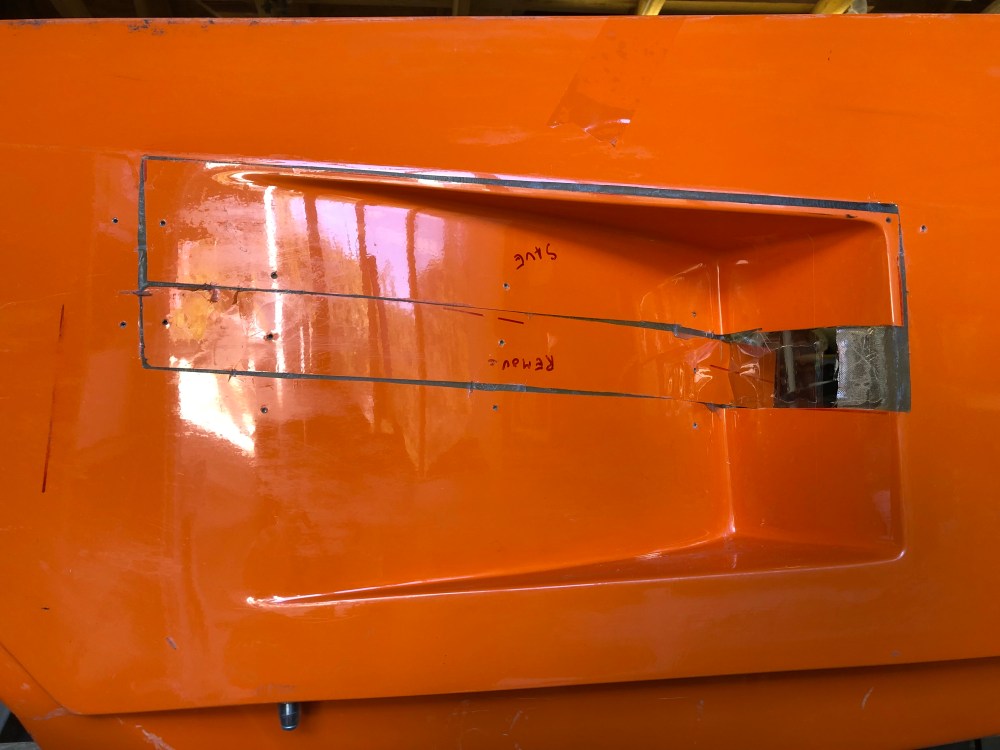
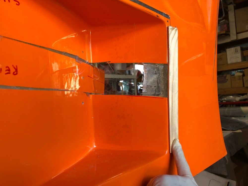
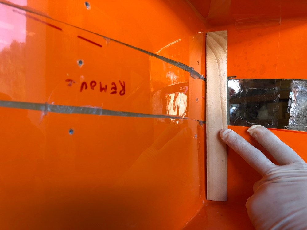
Tracing out my cut lines; the forward (left) cut line is placed vertically, as is the rear (right) cut line. I decided to place my cut into the intake about halfway up the existing form. The top line follows along the same angle as the lower; which is defined by the diagonal feature. I gave myself just a little room above the feature so I could preserve the turn. The ~3″ piece between the diagonal feature and the intake will be saved to patch things back up.Cuts made; note the rear (right) cut is made about an inch behind the edge of the intake. I did this to preserve a nice flat edge that I’ll use later to position the piece I cut out. Similarly, the forward (left) cut is made in an area where the bodywork is flat.What the new intake will look like.(Note the bodywork is now upside down). I used pieces of L-metal to secure my patchwork. The screws used to secure the bodywork will cinch up on each piece, drawing it up flat against the L-metal and aligning each piece relative to the other. To get the center “strip” flexible enough to take the contour, I thinned it down using a belt sander.Aluminum tape used to seal all the gaps. The aluminum tape is stiffer than packing tape and can be pressed down to get a good seal on either side of the gap.Lots of screws! The protruding tips will make it difficult to lay down fiberglass cleanly …… so I whacked’em off using an angle grinder.Aluminum tape works well to bridge gaps such as these. It’s stiff enough to lay resin into and won’t flex much when stippling resin if applying to CSM.To help fill the gaps I first applied resin then followed up with reinforced (Cabosil + milled fibers) resin. After setting up, I followed up with 2 layers of CSM, sandwiched on either side by a layer of fiberglass cloth.Once the intake was all patched up I secured a piece of taped cardboard to edges where the intake hole will be cut. Here, I’ll build up a flange that will be used to secure the oil cooler duct.Reinforced resin to fill the corner and create a fillet so fiberglass can bridge the two features. Too sharp a fillet and it’ll be difficult to get a bubble-free joint.The Frank-intake mod is complete! Some more patching to blend everything in but it’s looking much better.Success – the relocated outside edge of the intake is still lined up with the original …… and the inner’s not looking too bad either!Stepping back; the modified intake flows much cleaner from front to back. I think this is how the bodywork should have been molded to start with.A slightly different angle; the lines definitely flow much cleaner front to back!
Front wheel vent patch [Bill’s mod]:
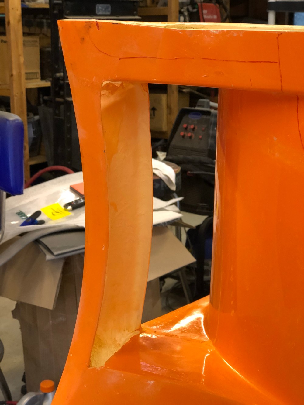
Just behind each front wheel is a vent which relieves high pressure air from around the wheel. This helps maintain front downforce – pretty critical when trying to balance aero loading imparted by the large rear wing. Due to how the body mold was created, it’s not possible to fully close out the vent feature – there’s a whole portion that is completely exposed (not normally visible when standing beside the vehicle). This area of the bodywork isn’t normally visible unless you’re bent over with your head shoved into the vent.
However, if you’re a spinning tire flinging dirt and debris all around as you’re rotating – you get a great view into the vent …
Here’s a photo of the vent opening taken from the perspective of the tire. This is a great place for dirt and water to migrate into the interior bodywork with no way out (if you’ve got wheel well shields in place).
Bill Phillips has a nice how-to in his build thread which talks about how he created his patch. I followed a similar procedure.
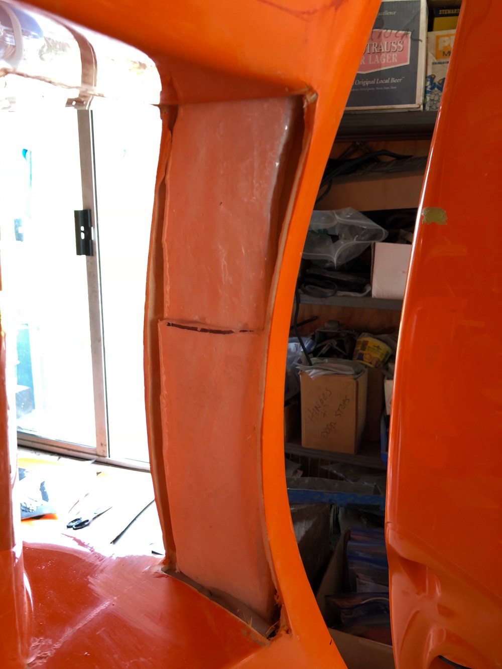
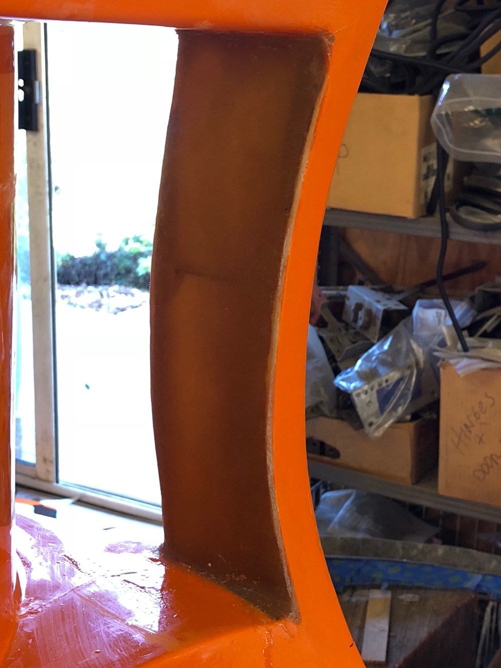
A couple pieces of taped styrofoam to give the fiberglass some backing.Initial fill was made using resin reinforced with 1/4″ chopped fiberglass filler. The chopped fiberglass is much more efficient for bridging the large gaps between the foam and existing bodywork. Milled fiberglass reinforced resin was then used to smooth out the surface and create fillets at the top and bottom edges.I once again used a combination of CSM and glass cloth to build up the face. The fiberglass cloth leaves a relatively smooth finished surface meaning less bondo work later.
This is a relatively minor modification but if you don’t want crap getting into the interior of the spider it’s a requirement. It also gives the car a much more finished look if someone should happen to be peaking down into the vent.
Rear wheel well contour modification [Howard’s mod]:
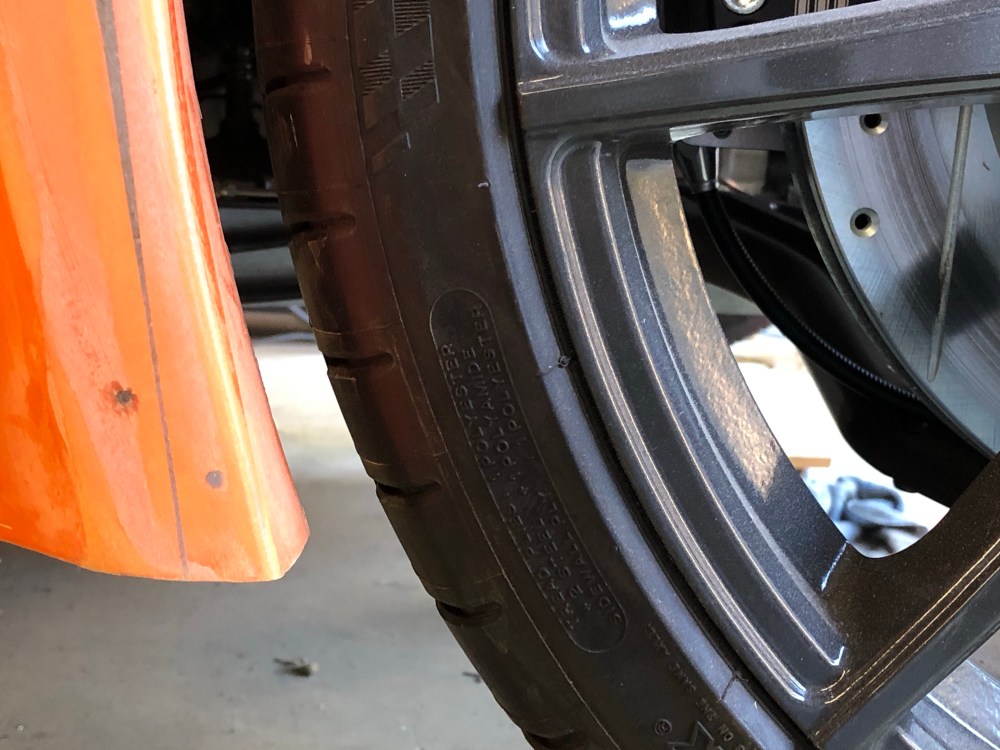
Credit goes to Howard for this modification. As I did with the front, I decided to modify the rear wheel well contour. When fully drooped, the rear suspension hangs low enough such that the rear wheel makes hard contact with the bodywork at the forward edge of the wheel well. To remove the rear tire you’ll need to use a jack to support the rear suspension, then carefully slide the rear wheel off after having removed the lug nuts. What a pain in the butt …
Again, I decided to remove approximately 0.5″ of material as measured along the lower edge. To define my triangular cut-out I placed 2 lines going to a point where the wheel contour turns vertical, see below:
Triangular shaped cut made; I targeted ending the cut at the point where the wheel well arc goes vertical. The new contour will flatten out starting at this point for a short period before curving back in toward the wheel.L-metal and aluminum tape in place, ready for some fiberglass!The inside surfaces were sanded down and beveled to give the new fiberglass sufficient surface area to grip. This modification will impart a fair bit residual stress in the assembly – sanding down the area where the cut ends will help relieve some of that stress but you’ll want to be sure you’ve got enough new glass down to hold everything securely in place.Another round of resin, reinforced resin, glass cloth, and CSM.The new rear wheel well contour. It’s a subtle change but this will give the rear tire enough clearance that it can be removed without the need for a jack. That stepped feature due to the joint mismatch will need to be sanded down; I used reinforced resin to fill in the area below the protruding edge.SUCCESS! Here’s a shot of the rear wheel at full droop; the revised contour gives sufficient room to remove the wheel without it binding between the studs and bodywork.
Now that a majority of the rough body modifications are complete I plan to shift focus back toward the interior of the car. With the interior complete, I’ll re-hang all the body pieces once again and pin the center spider down so I can finalize attach points for the front and rear clam. With things pinned down I’ll be able to final fit the doors and make serious tracks to getting this thing ready for final bodywork, paint, then onto the road!


One Comment Add yours