28. Full of hot air

on

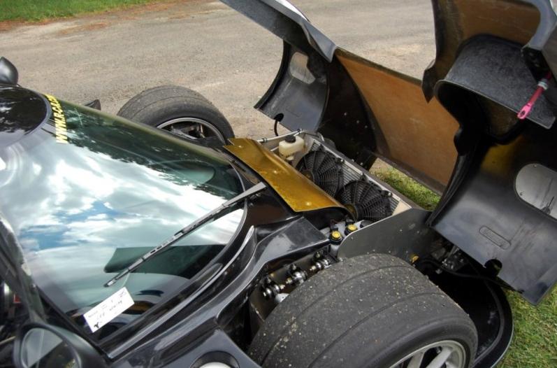
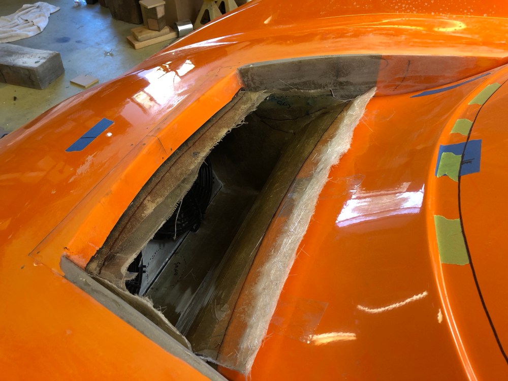
It’s not enough to just make the radiator exit bigger – air management under the front clam is of critical importance if you want to manage engine and passenger compartment heat.

If radiator discharge air is allowed to flow freely out it will then crash into the components in the radiator box, heat up the foot box, then squirm its way through a too-small opening.  This results in poor flow through the radiator and adds a TON of heat to the passenger compartment – not to mention killing your battery if you’ve opted to locate it in the radiator box.

Screen Shot 2018-03-04 at 7.00.08 PM.png
Front clam cross-section showing an empty radiator box.  Flow is chaotic and uncontrolled and allows fully heated radiator air to blow against the passenger foot box.  The uncontrolled nature of the flow creates a fair bit of disturbance, likely leading to even less flow through the factory hood vent.

The factory offers a heat shield to protect the foot box and battery from excessive heating.  With the addition of some insulation/thermal shielding I’m sure the factory option does a great job of keeping things behind it cool.

Unfortunately that’s about all it’s good for.

It’s a fairly basic design and has a vertical surface located (too) close to the fan exits.  The tight spacing to the fans combined with its near vertical surface causes the flow to choke down, effectively reducing the ability for air to flow through the radiator.

SL-C-4
Factory option; fiberglass heat shield (gold reflector added, not included from factory).
c4f9a785-c0c6-4ef9-941c-e016c855dfdd
Another view of the factory heat shield.  Note proximity to the fans – and this build isn’t using a fan shroud.  If using a fan shroud you’ll lose another ~1 inch of clearance.

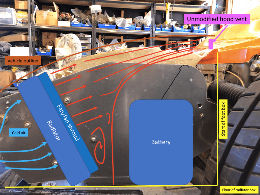
My guess at what the airflow looks like …

Screen Shot 2018-03-04 at 7.03.01 PM.png
Factory heat shield option installed; great for doing what it’s supposed to – shielding the battery and foot box from heat.  Unfortunately it’s butted up so close to the radiator discharge that it really chokes down on the airflow.  A fairly large recirculation zone likely forms in the lower half of the discharge.  The heat shield design *does* help smooth airflow as it moves toward the factory hood vent.

Secondary issues with this design is it’s blowing hot air over the brake and clutch reservoirs and makes fitting a fan shroud more difficult.

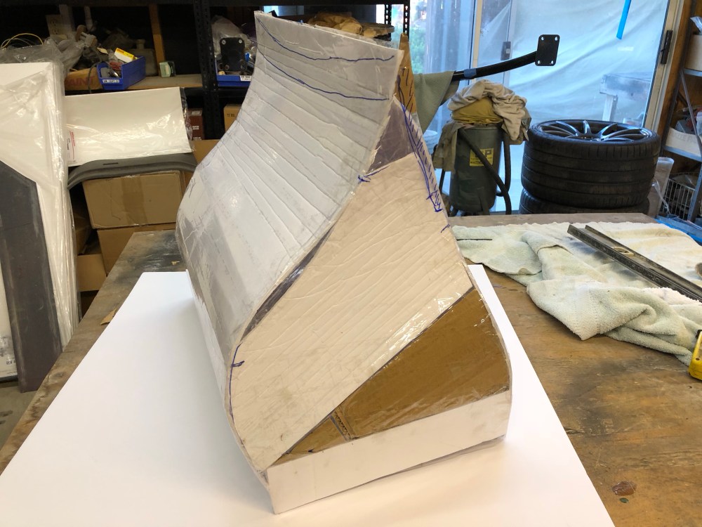
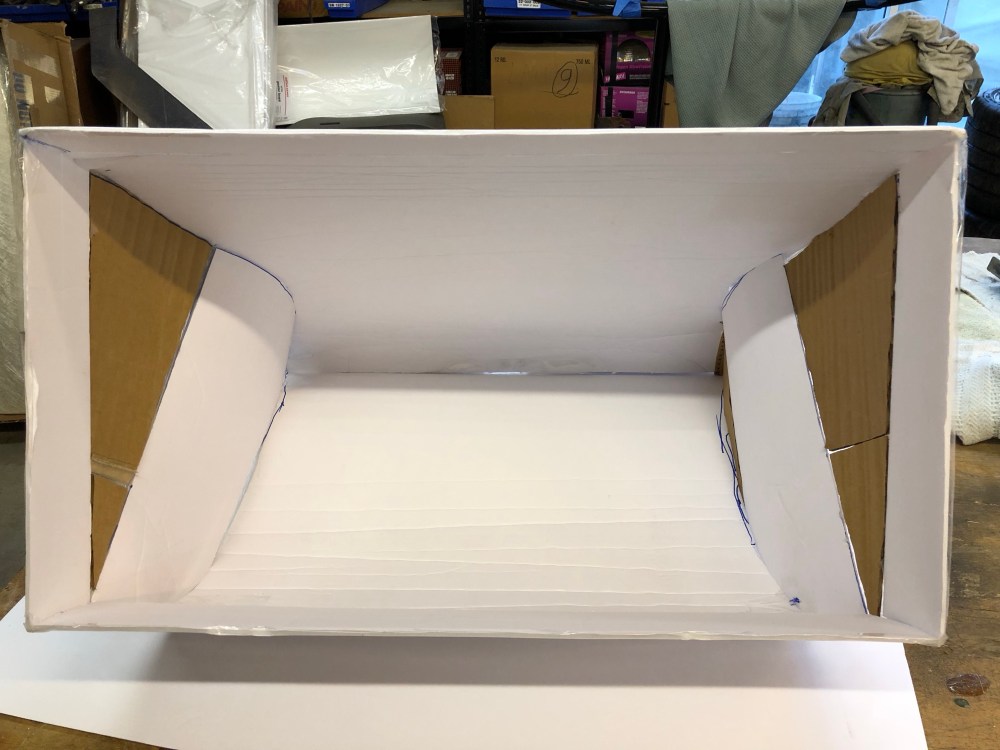
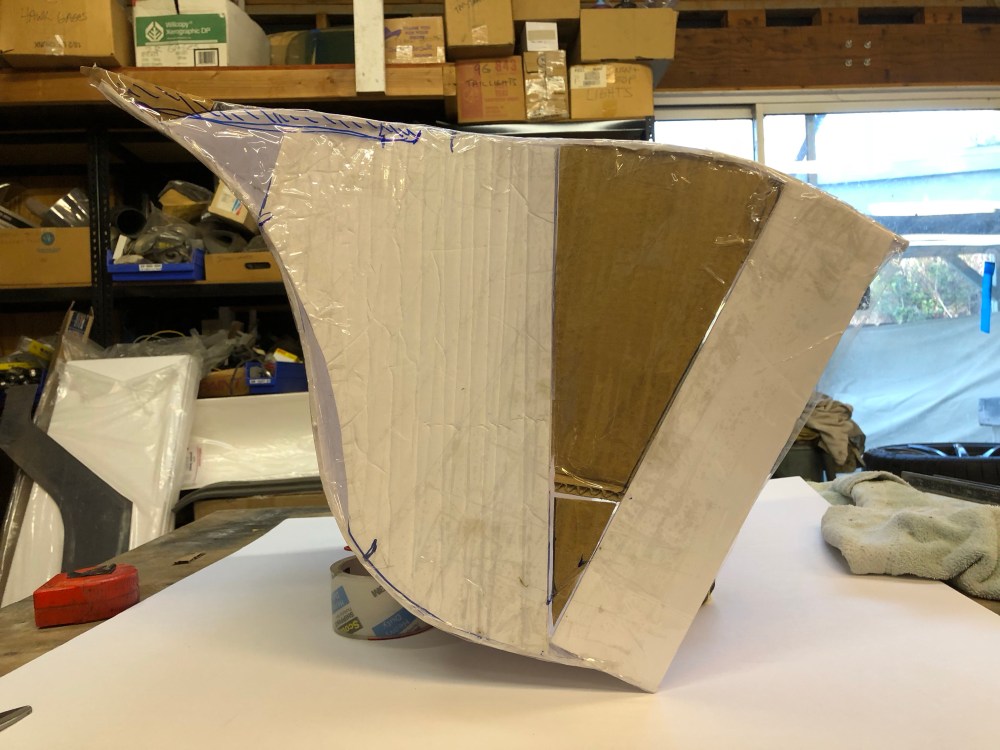
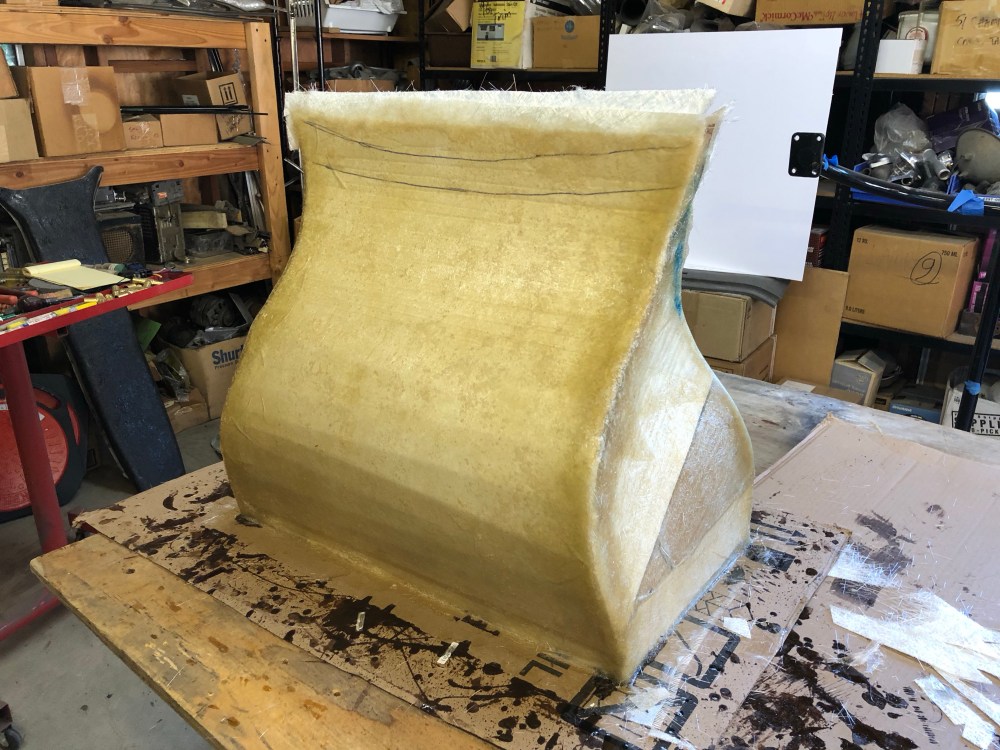
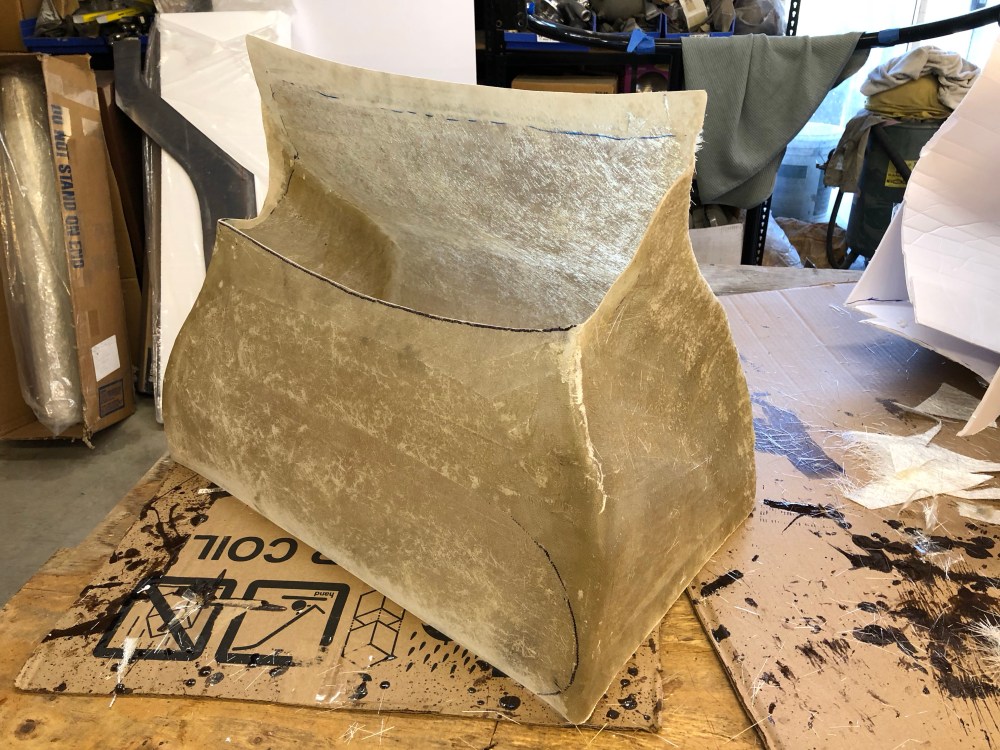
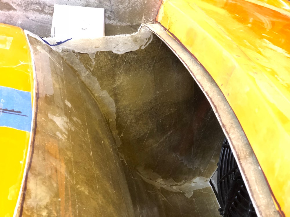
My solution to these issues was to fabricate a duct that could be fitted against my fan shroud.  The idea is to give as much room as possible for the radiator air to flow out and gently bend toward the hood vent.  Increasing the hood vent size dramatically decreases radiator backpressure and increases the minimum flow cross-section.  This was the primary motivator for me locating the battery at the back of the car – even though it meant more mass to an already rear-biased weight distribution.

img_9627
Cardboard plug with packing tape for a release agent.
img_9626
Bends along left and right edges to clear brake/clutch and ramlift reservoirs.
img_9624
“Top” of duct; upper half will be where air exits through the hood opening.
img_9628
View from the radiator fans; I ended up goofing the plug along the lower edge.  I had intended to have my duct fit over the entire fan shroud; but I must have pinched the lower edge slightly when I applied the packing tape.  If making one of these, I recommend making it oversize by ensuring the cardboard can fully slip over your shroud (I tried to make mine line on line – a mistake).
img_9623
View from the side; the upper curve follows ~1″ below the surface of the front clam.  I want to preserve a good bit of the “lip” at the vent opening to keep the front clam as stiff as possible – so I opted to keep the duct a bit shorter than it could be.  Blue hash marks along upper left edge denote vent opening.
img_9640
Glassed; I started with a layer of glass cloth and followed up with two layers of chopped mat.  Edges/corners are reinforced with another layer of cloth.
img_9648
Rough fitting the duct and drawing trim lines.  These edges will need some more clean-up to look presentable; I’m planning to hide everything with some type of honeycomb grill material.
img_9656
Trimmed duct.
img_9661
View from the inside.  Interior corners will need filleting for stress reduction and attachment flanges will need to be added.
img_9663
Trimmed duct installed.
img_9669
Not much room between duct and AC drier.
img_9665
Side view.
img_9652
With front clam installed; discharge is well aligned with front of spider.  Forward lip will be trimmed back at a later date, I’m still working on how it’ll transition to the front clam.
img_9654
Profile of duct; lower edge runs almost parallel to floor of radiator box before it curves up then back toward rear of vent opening.

What I think is going on …

Screen Shot 2018-03-04 at 7.10.25 PM
This is a very simplistic 2D representation of what I (hope) is happening in the duct.  Maximizing the distance between the fans and duct wall gives discharge air maximum space to turn gently and minimizes the recirculation zone along the lower edge.

Making the cross-section at the duct entry increasingly larger than the radiator discharge creates a decrease in local air pressure, thereby promoting flow through the radiator by reducing backpressure.  My hope is that the recirculation zone is relatively small.  The lower edge won’t be sealed against the fan shroud; some air “bleed” into the radiator box may further reduce this recirculation zone.

Chaotic airflow management – check.  What about heat management?  I plan to cover the entire duct with heat shielding.  This will (hopefully) keep all that heat energy coming from the radiator away from the bodywork and from the passenger foot box – getting it out before it’s able to transfer much energy into the car.

I then made up some attachment flanges; this duct will remain fastened to the chassis when the front clam is removed.

img_9715
Front edge will be secured to top face of fan shroud.
img_9714
Rear edge will be fastened to forward part of spider.
img_9716
Lower edge will be fastened to lower rear face of fan shroud.  I used a combination of cloth and glass mat to get strength and stiffness.

That’s a lot of hot air about hot air!

2 Comments Add yours

Leave a Reply

Fill in your details below or click an icon to log in:

WordPress.com Logo

You are commenting using your WordPress.com account. Log Out /  Change )

Facebook photo

You are commenting using your Facebook account. Log Out /  Change )

Connecting to %s