I was on a real roll over December and January with my progress and posts. I haven’t had much time for the car or posting lately; several work trips and a family vacation have made it difficult for me to stay on track. However, I have been making progress when time permits.
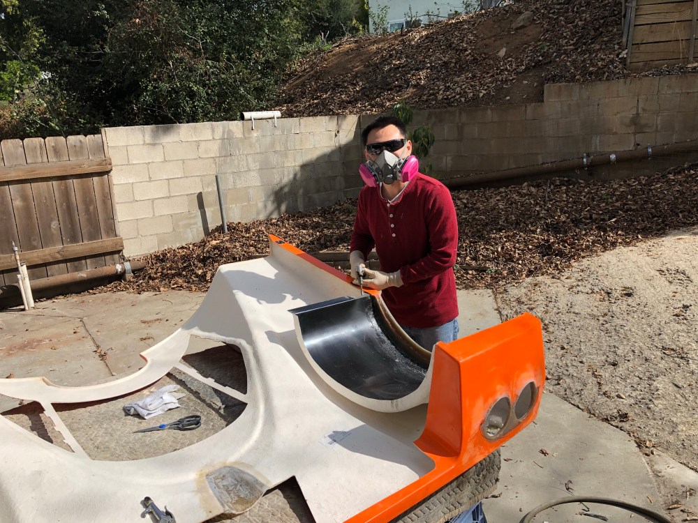
With most of the mechanical and electrical work squared away it was now time to turn my attention to the bodywork. This is the area of the build which I approached with the most trepidation – I’ve never really worked with composites before and getting this really wrong could make a nice looking car look like it was pieced together by a 10-year old, regardless of what cool stuff might lay under the hacked up body.
To keep my expectations in check I’ve been reminding myself this is going to be a 5-10 foot car; it’ll look great from afar but at 5-10 feet the warts will be somewhat obvious. I think if I can pull this off, I’ll be pretty happy with myself. (Of course as I type this, secretly in that part of my brain I won’t acknowledge, I’m hoping it’ll turn out to be supercar OEM level – LOL, it won’t).
Many thanks in particular go to HJones and JMolleur for giving me a ton of pointers before I got myself into trouble. As they say – the first cut is the deepest (and scariest!). As delivered, the gelcoat body is really nice (IMHO). Pros who work with this material on a daily basis may beg to differ, but coming from someone who doesn’t know the intricacies of what a “great” fiberglass body is, this body looks great! I’ve heard many builders will just clean up the parting lines, buff the gelcoat, and call it a day. While this is more than acceptable for a track car, it’s maybe just a smidge below what I’d want to run around in for a daily driver. There are areas where it’s obvious the gel coat has bubbles near the surface and some tweaking of surfaces is needed. So – paint is planned, but that and body hardware will be covered in a later post.
Before I can even get into attaching the body hardware there are several key modifications I felt were needed. I’ve been spending a surprising amount of time working on the body – I really didn’t expect to be doing this, but there are a bunch of little areas I felt needed to be addressed before I could be happy with the end product. Not making these changes would have shortened my build time significantly, but some of these changes are things that drive my OCD nuts, and others I felt were necessary to make the car acceptable.
As an aside – I recently bit the bullet and put a few nickels toward paying for this blog. What’s that mean? MORE PICTURES, dial-up users beware! (Does dial-up even exist anymore?) For the last little while I’ve been trying to be selective about what pics I put up because I’ve started to float closer to my free hosting limits. WordPress was running a promotion over Valentine’s and I decided what the heck?
Just about everything discussed below is still in progress; I’ve been “kicking the ball” and jumping from panel to panel, component to component, trying to keep the ball moving on a bunch of different areas. Can’t seem to zero in on closing anything out until I’m closer to “final” assembly.
So let’s jump to it!
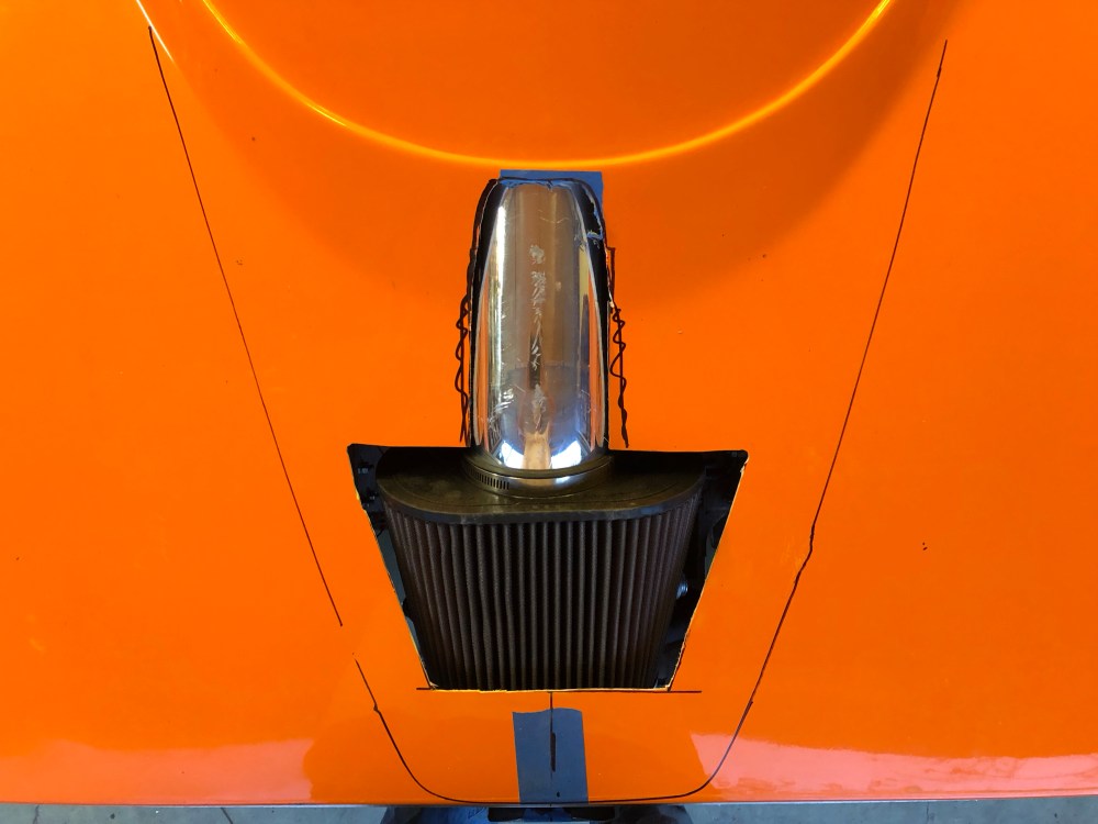
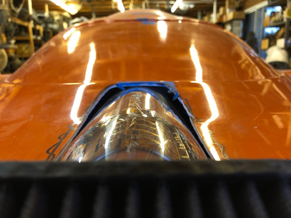
Air filter/intake tube clearance:
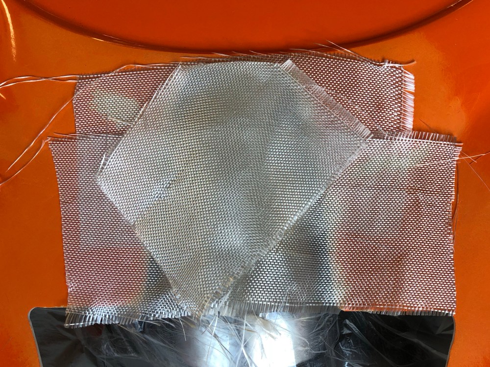
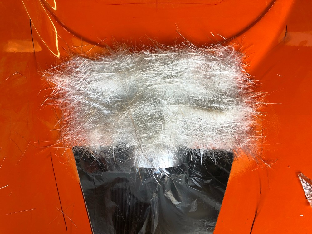
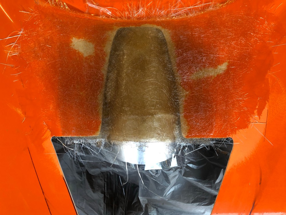
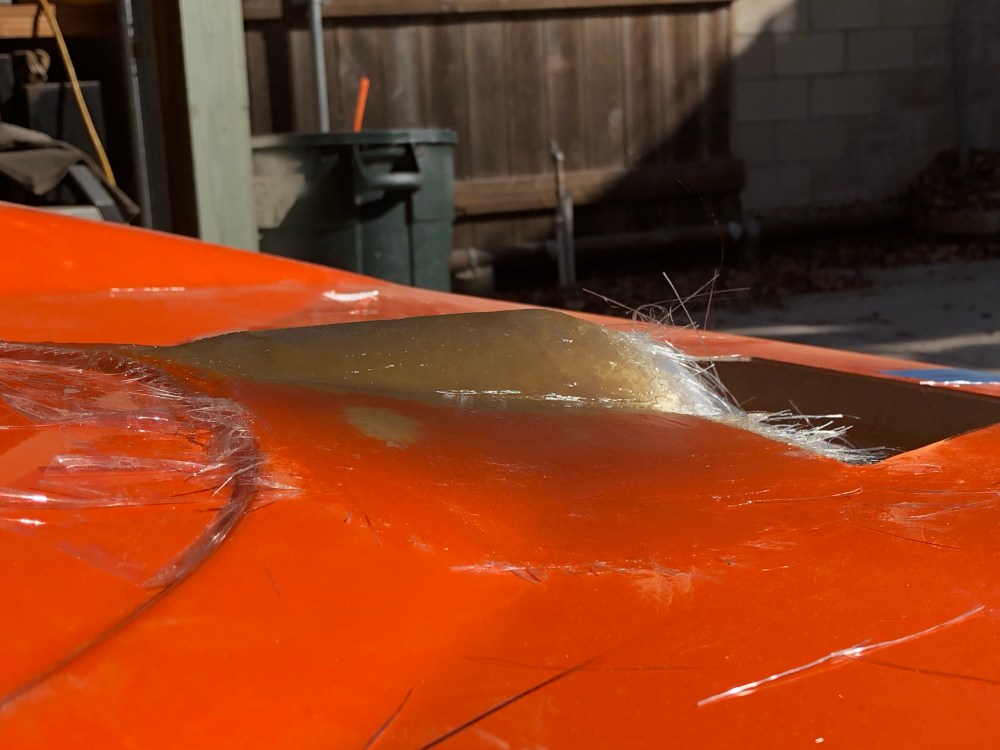
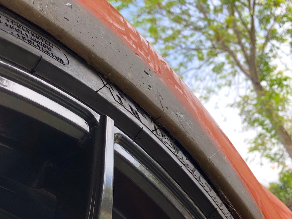
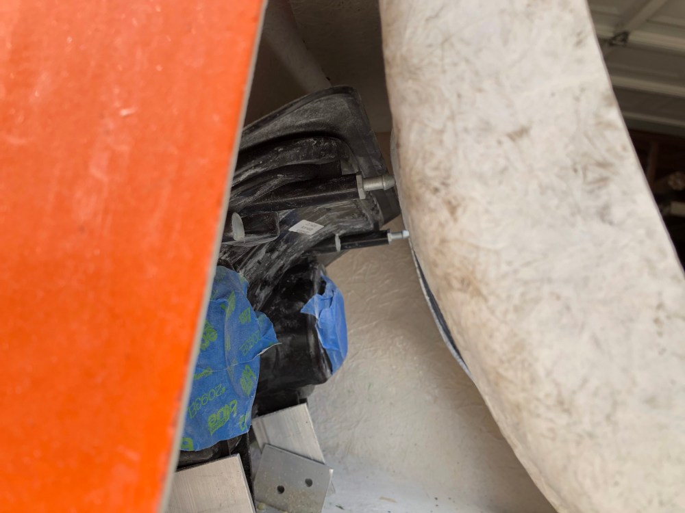
This modification is required if you’re running the “standard” Sceptre Performance 4″ pipe to connect your air filter to throttle body. Before you can properly position the rear clam, a hole must be made to allow the pipe and filter to peak up above the bodywork. The cut comes exceptionally close to the rear glass. I was planning to use the rear intake cover that JMolleur produces (contact him on the GT40s board for availability/pricing); however with the cover positioned the intake pipe is still visible. To hide the pipe, I roughened the area on either side and added a glass patch so the pipe would no longer be visible once the cover is installed.
Part numbers used:
- K&N air filter, PN RF-1034
- Spectre Performance 4″ tube coupler, PN 9771
- Spectre Performance 4″ intake tube, PN 97291
The intake tube has a fairly long straight section, then a 22-deg (mandrel bent) bend. The straight section is too long as-delivered and will need to be cut down to fit within the tail bodywork. I cut the straight section such that the bend lined up with the rearmost bar of the rear chassis brace. The GMPP MAF sensor will then need to be welded in no less than 10″ away from the throttle body opening. The portion after the bend doesn’t need to be trimmed.

To do:
- Finish smoothing out the glass patch.
- Fit the air filter scoop.
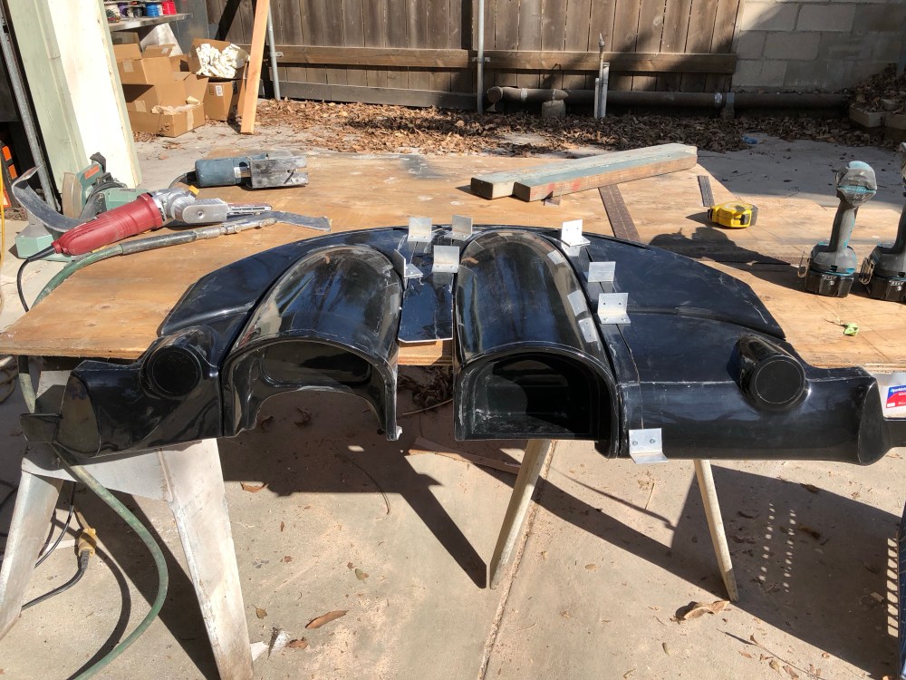
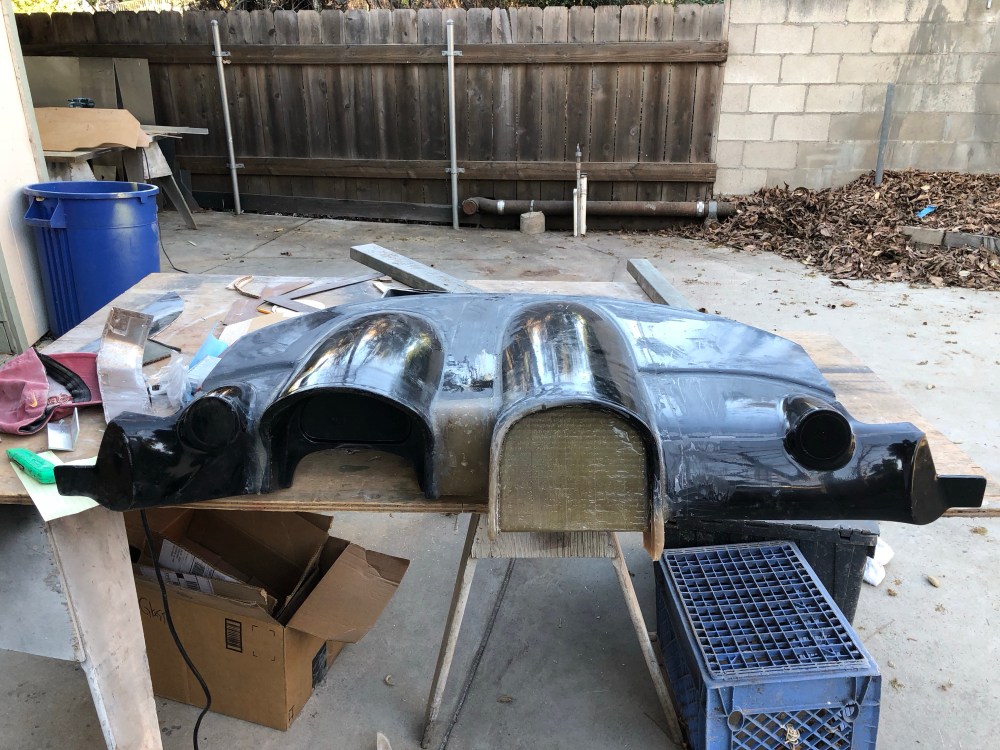
Taillights:
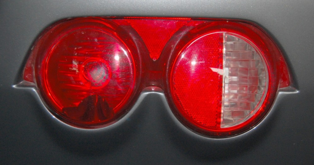
I already knew before ordering the kit that I did not want to use the factory supplied taillights. They look outdated and I wasn’t really a big fan of the little triangular cutouts on either side of the assembly.
I’ve searched for countless hours and couldn’t come up with a nice, dual round taillight configuration I cared for. I had originally thought about performing the Lotus COB taillight update (an exceptionally well documented how-to can be found here). After considering it for some time I decided I just didn’t want to tackle this project. I also didn’t want to think about the amount of work I’d have to go through to repair the lights should any of the COB boards go out. So I needed a more readily available solution – which I just couldn’t find.
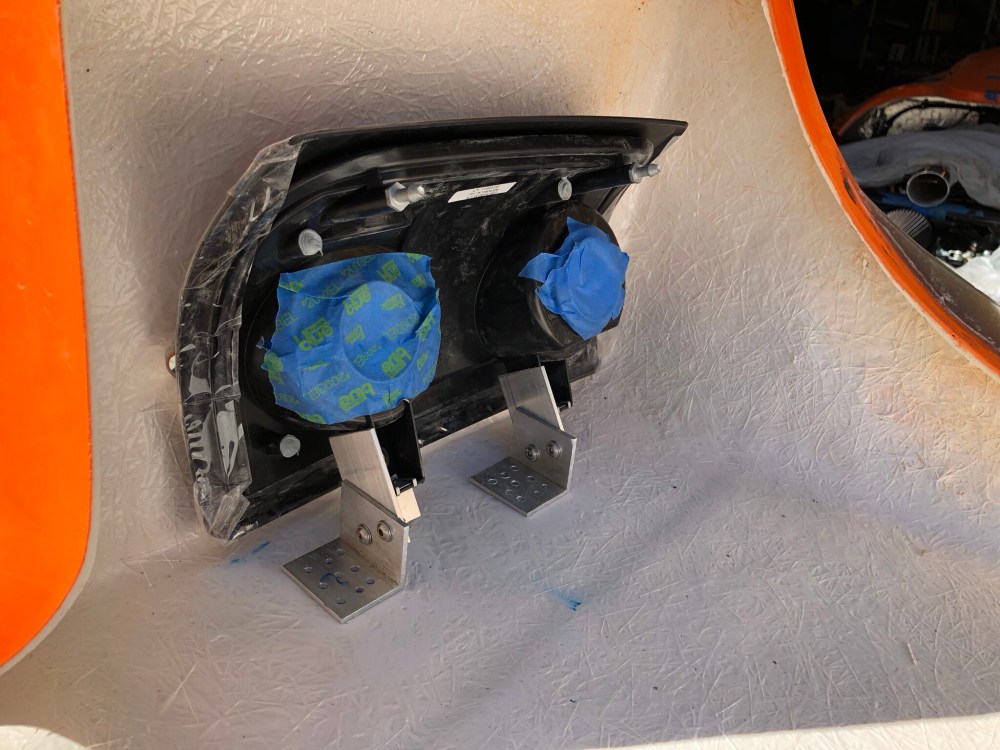
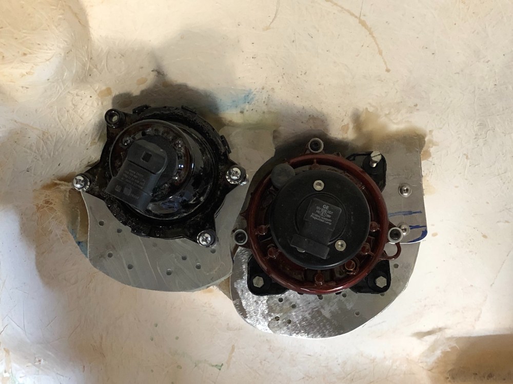
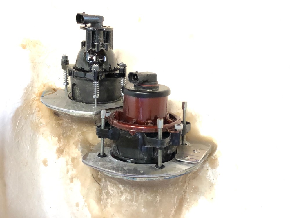
I’ve seen JBurer’s car in person (Allan’s #17 car) and I really like how the taillights looked on his car. Instead of using the factory supplied lights from a Dakota, John used the IPCW “Bermuda Black” LED tail lights, PN LEDT-404CB. Additionally, Allan had filled in the triangular cutouts – this is a much cleaner install than I’d seen on other cars.
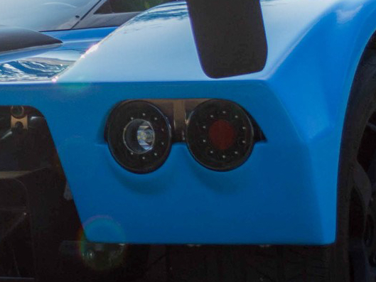
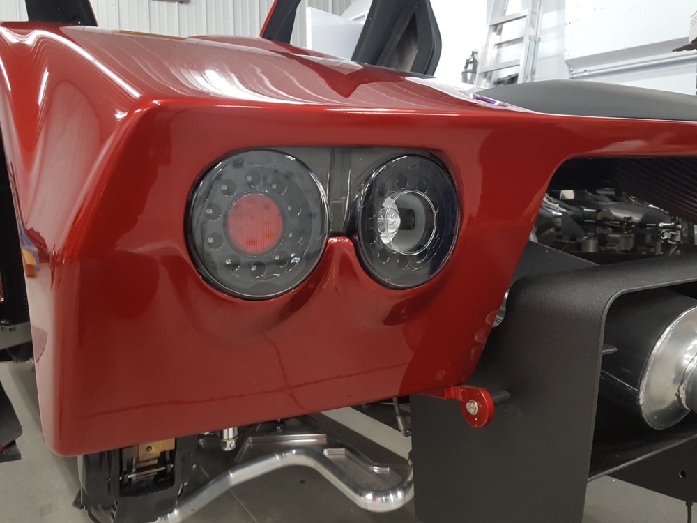
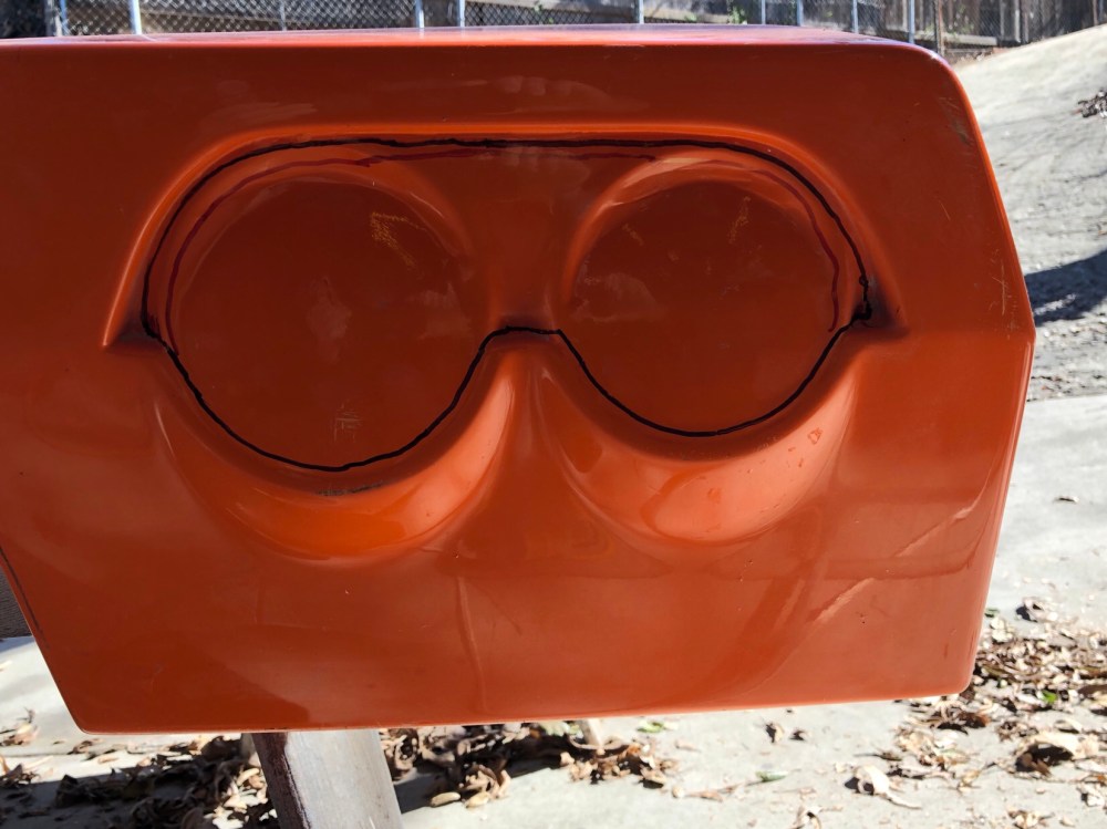
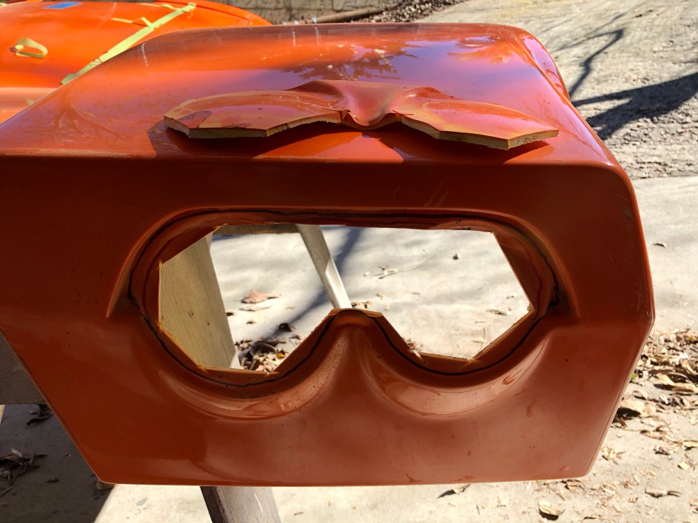
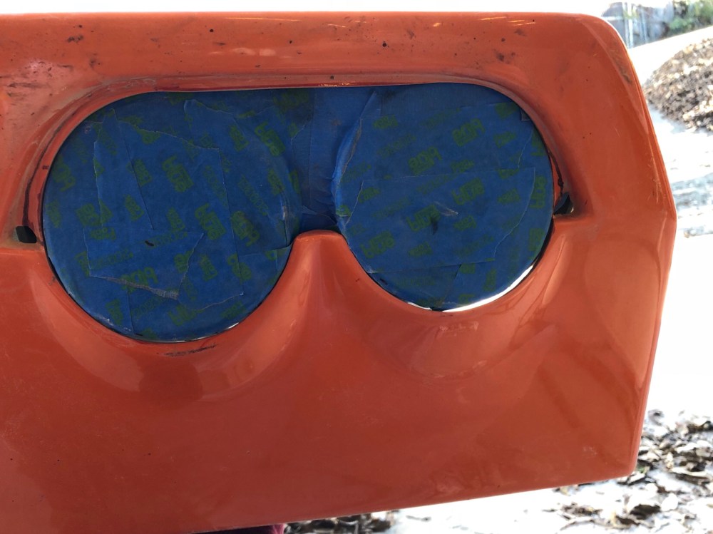
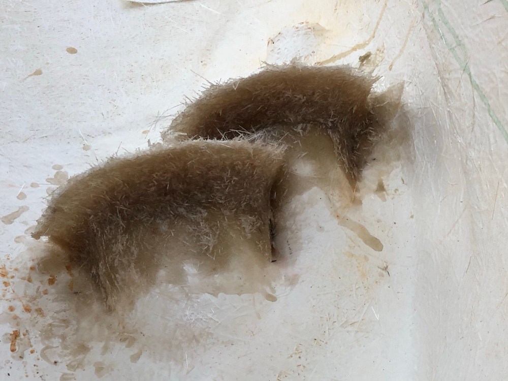
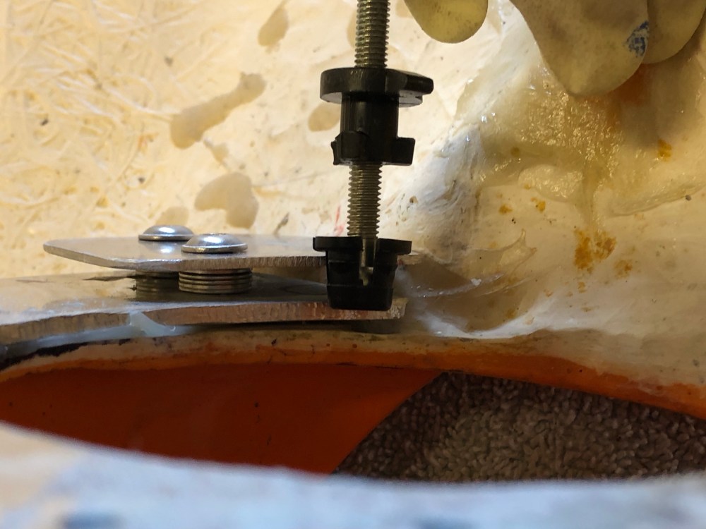
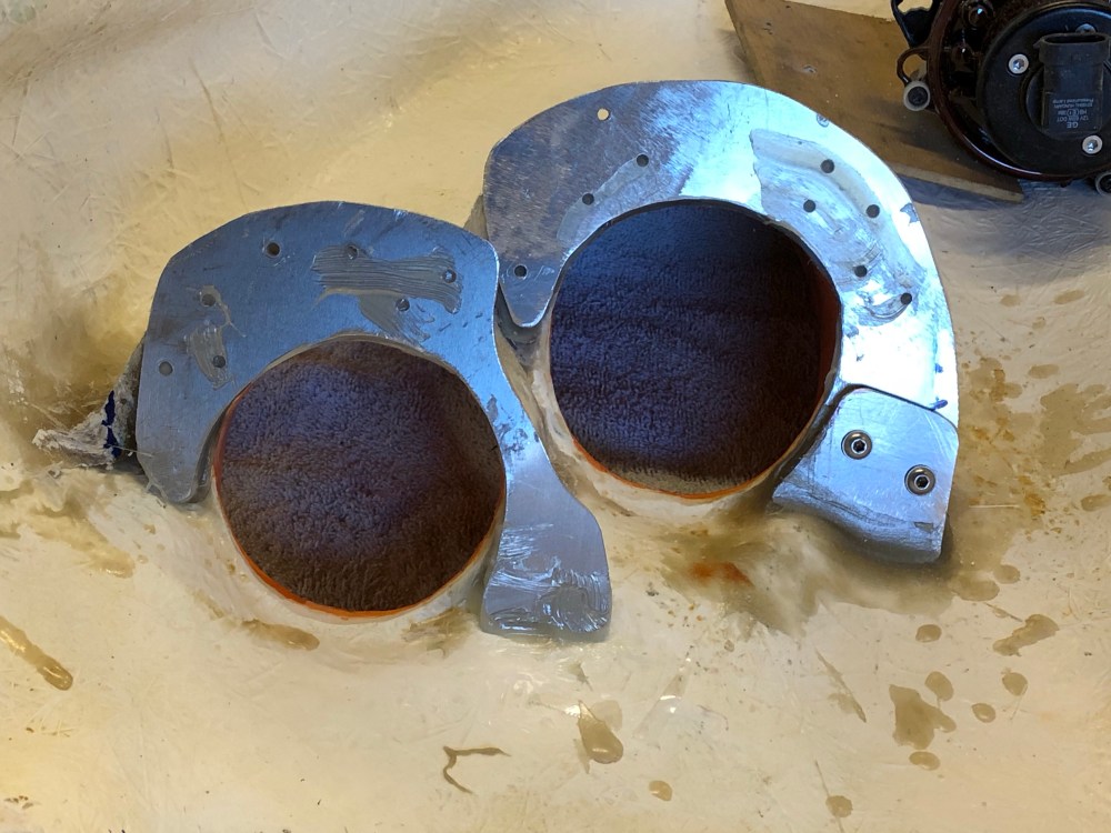
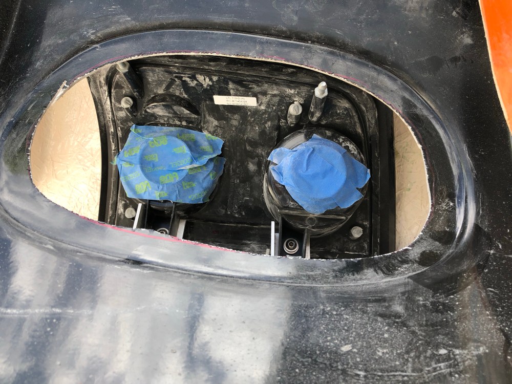
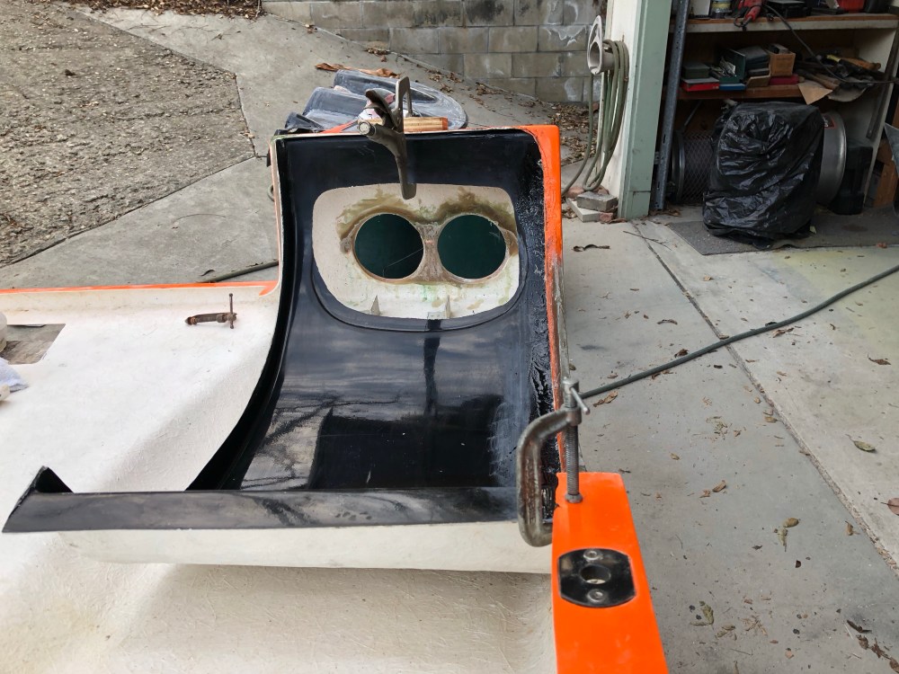
After staring at it and thinking about it more than I should, I decided I really want the dual round taillight look – so I glassed in the space between the two circles. To help get the glass right I taped the assemblies up using packing tape and glassed right onto the lenses. CAUTION – I think I may have damaged one of my lenses by leaving it in place for too long, exposing the plastic to the exothermic reaction of curing resin. I can see little micro cracks on the lens cover of one of my taillights; I tried to remove the assemblies before the resin had fully hardened so avoid exposing the lenses to too much heat. I also gave the lenses a quick wipe-down with acetone to remove some resin that had made its way past my masking. I’m not sure which caused the micro-cracks to form. Either way, Cam fail.
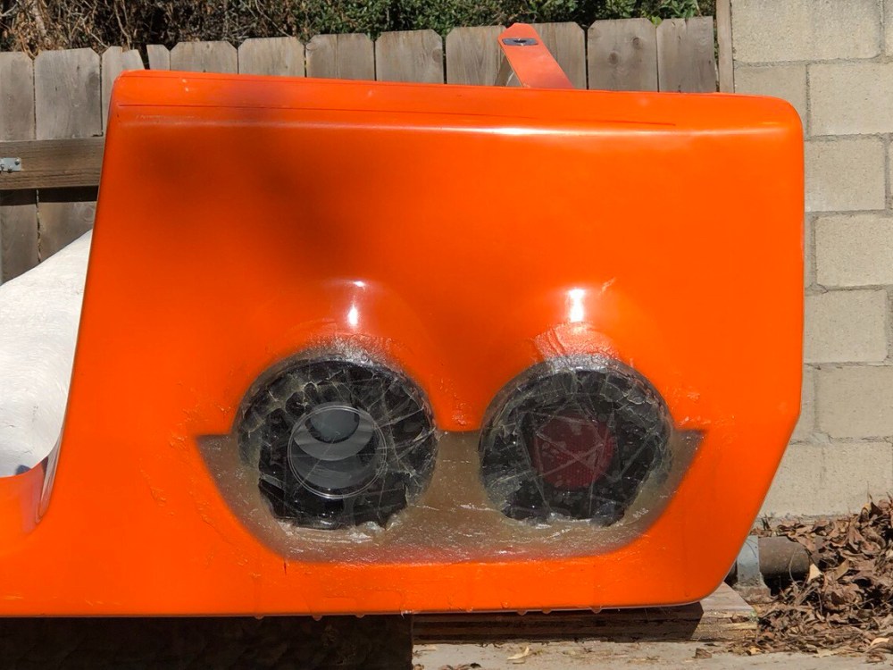
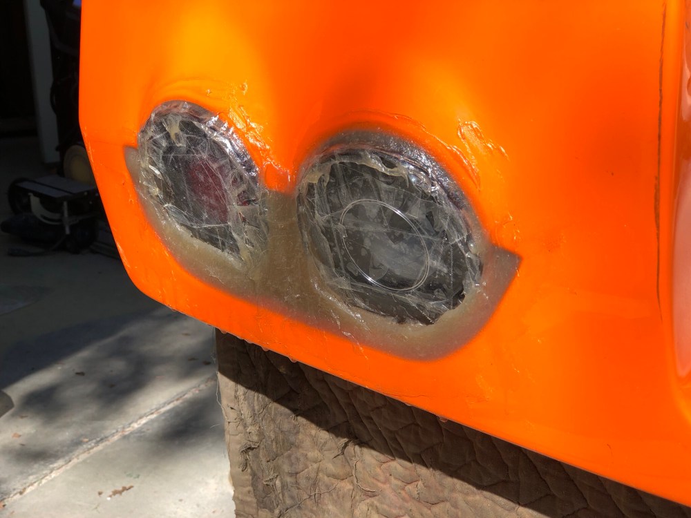
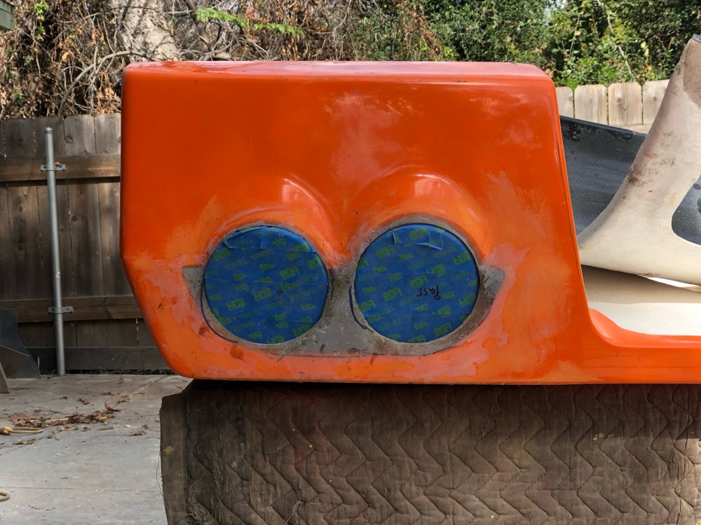
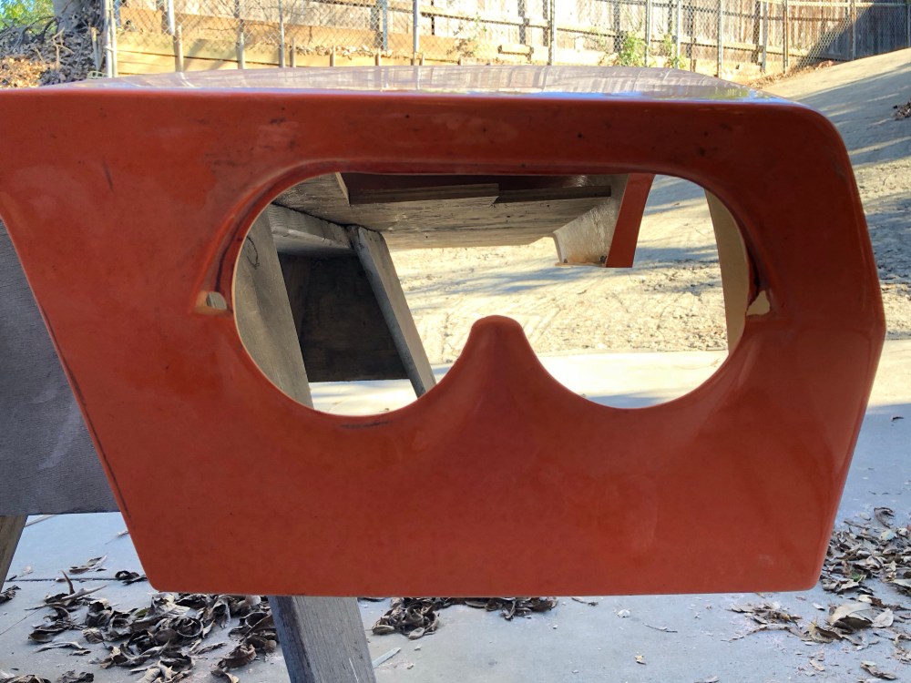
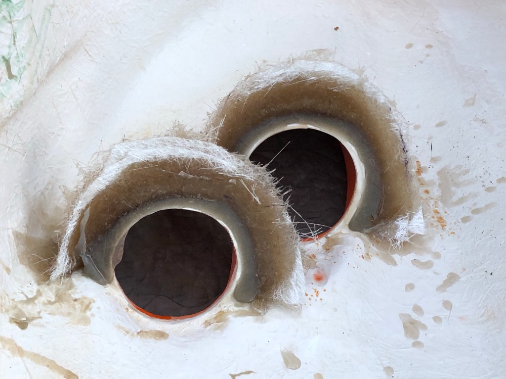
Since I’ve filled in the area above the circles, they’re set into the bodywork pretty deeply. I’m still playing around with how to shape the upper portion of the circle so it looks right. However, I’ve now got the 2-round taillight look, they’re a more updated LED design, and the relative difference in height for each circle is de-emphasized because there’s no longer a parallel line bridging the two circles together.
To do:
- Complete contouring of the cutouts.
Rear window louvers:

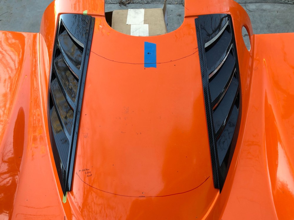
Bill (Rumbles) build thread discusses stiffness of the rear clam and how it can be difficult to open the rear clam with only one person due to it twisting while pulling up on the shell. He’s bonded some fiberglass reinforcement along the upper and lower edges of the rear window for increased stiffness. I’ll test this out once I get my hinge figured out and may come back to reinforce these areas as well.
To do:
- Measure and trim rear window.
- Install window and louvers.
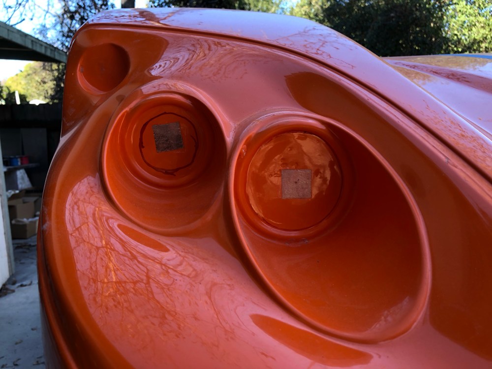
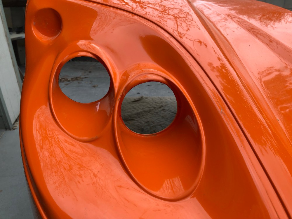
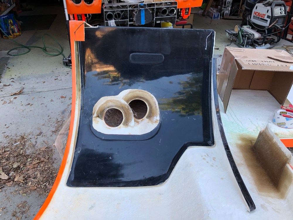
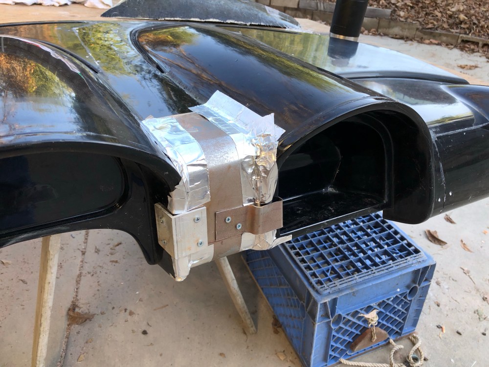
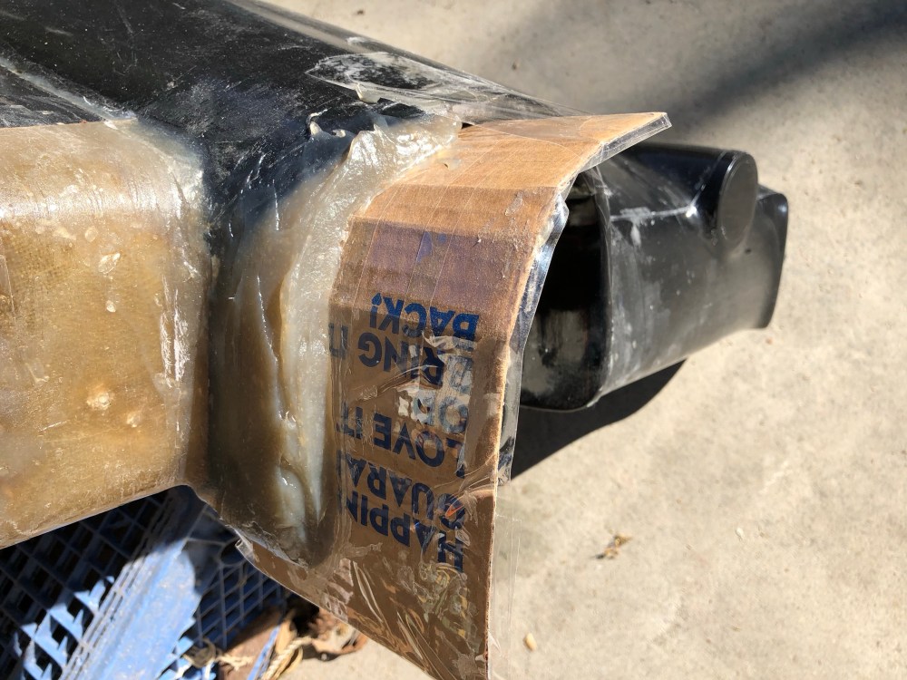
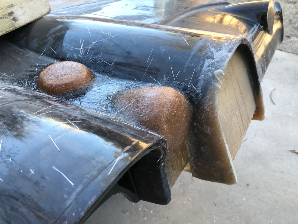
Fuel filler/access port:
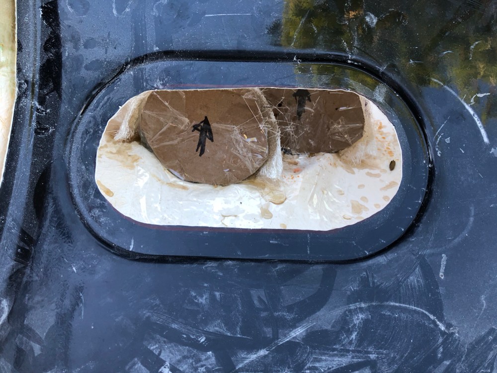
The next issue came at the fuel filler door. The molded cut lines/opening for the fuel door isn’t quite round. It’s a bit oblong and if you cut it per the molded lines it looks pretty terrible. I’m not sure if this is an issue specific to the race tail mold – I’ve seen it on several race tail builds but haven’t really noticed it on those with street tails (though I haven’t seen high-res photos of this area on a street tail build).

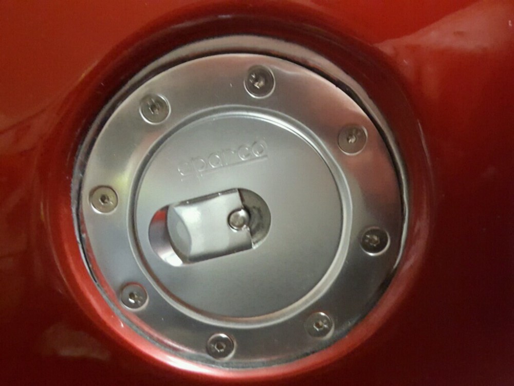
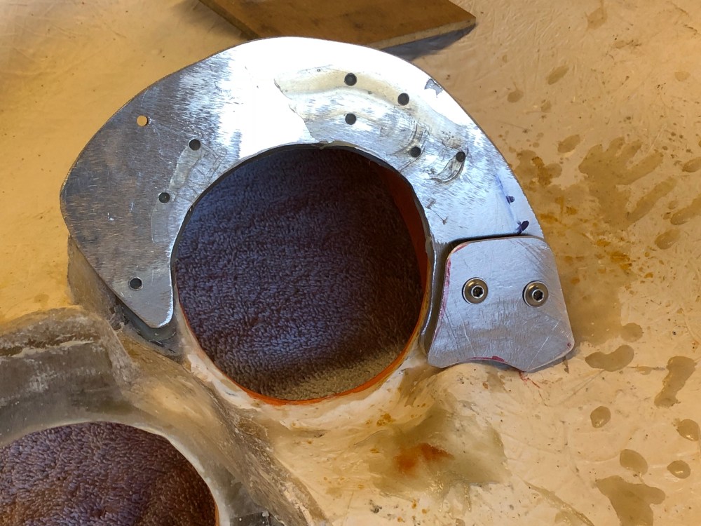
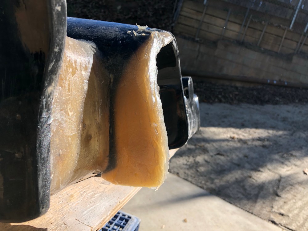
I’ve seen this phenomenon on several other race tail builds and it’s apparent even in lower res photos. It’s a total eyesore and drives me nutty every time I see it. To address this, I mixed up another batch of resin “peanut butter” and built up the area around the opening along the exterior body panel (the rear clam). I then cut the access hole to match the round form below, on the spider.
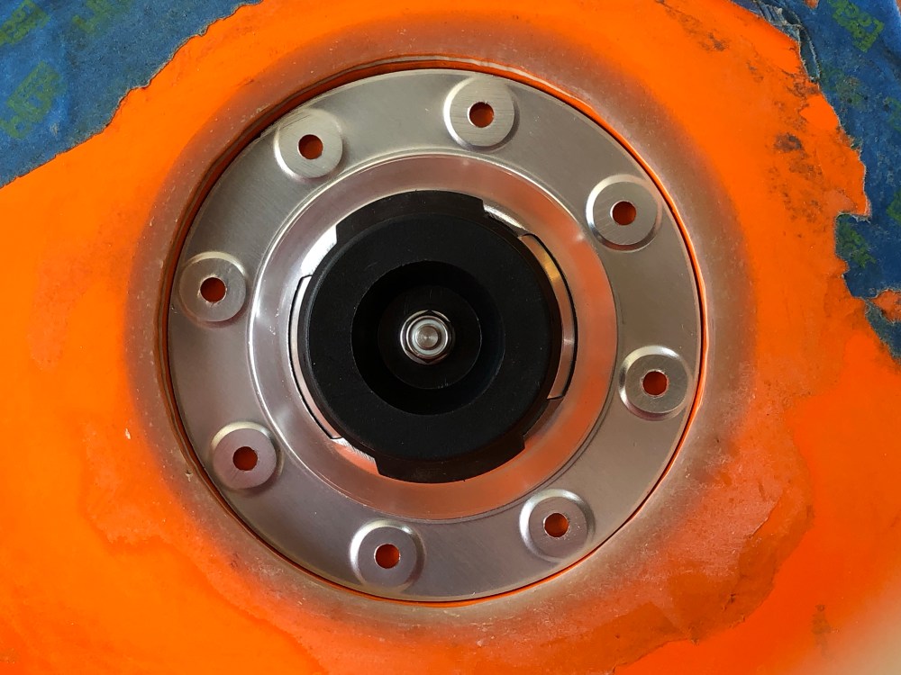
The exterior surface contour matches the contour of the rear clam while the access hole itself matches the features underneath. A gentle radius needs to be added next though I’m holding off on doing this until I get the Sparco piece installed. I may open up the ID just a bit more to account for any misalignment of the rear clam. When you have 2 circular forms so close together and it’s obvious they’re supposed to be concentric, any misalignment is really evident – much moreso when one of those features isn’t actually round!
To do:
- Install fuel filler door assembly.
- Finalize blending of fuel access port.
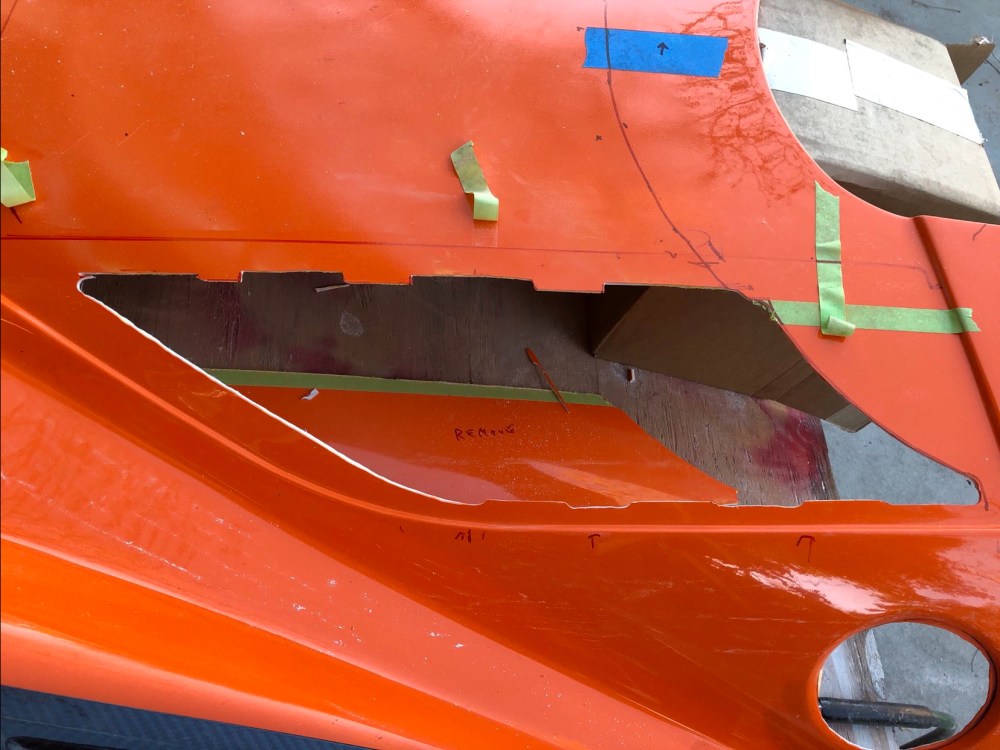
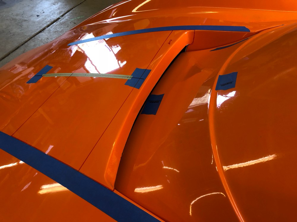
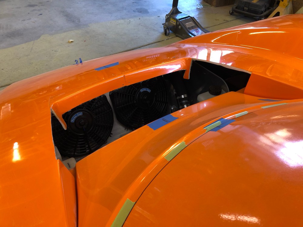
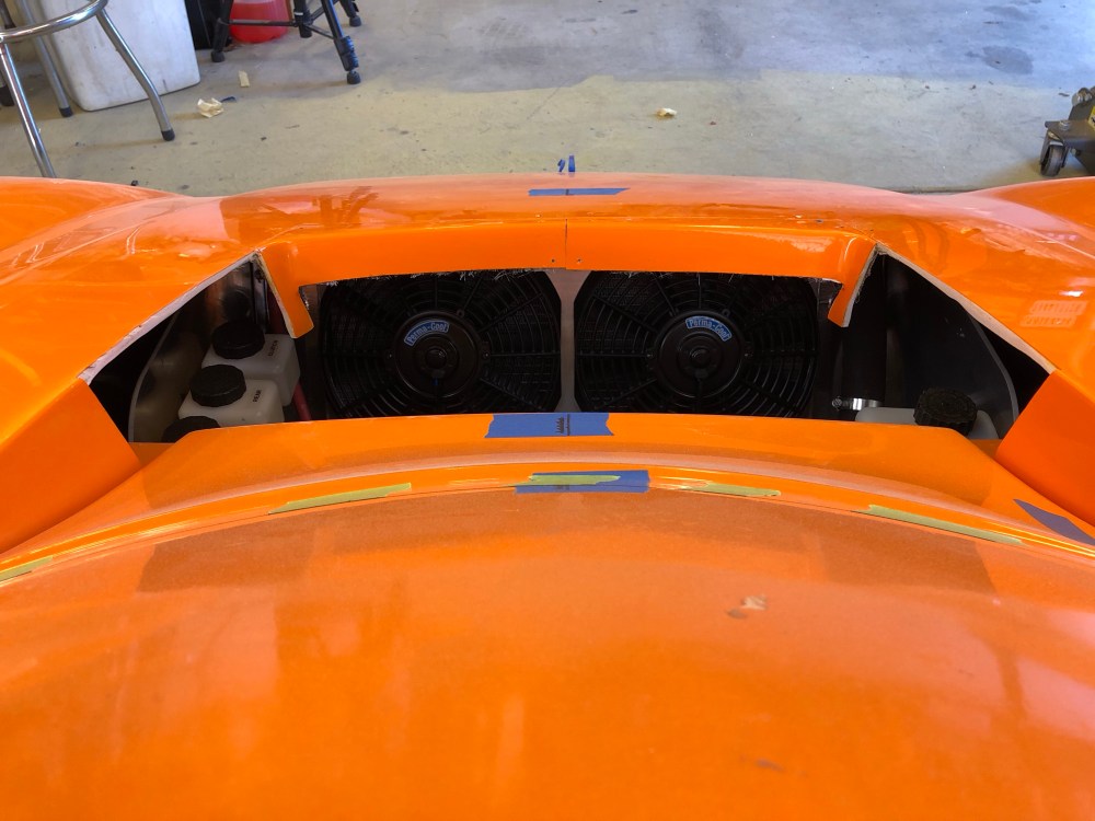
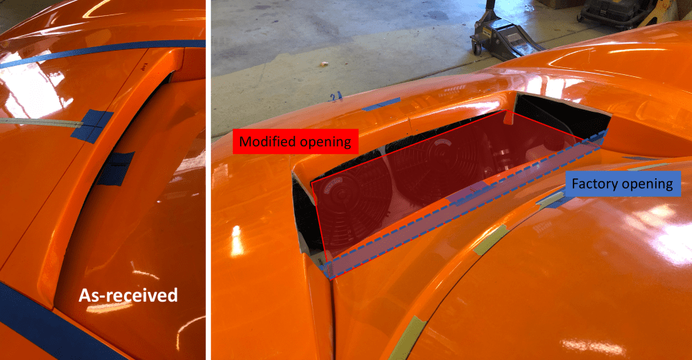
Hood/radiator exhaust vent:
The front clam isn’t necessarily designed to be mounted to open forward clamshell style, but many builders opt to incorporate this design feature regardless. The manual or wiki cautions against making this a hinged opening due to risk of damage in the case of a wind gust causing the hood to fail or fall over. The jury is still out as to whether I’ll make this a hinged opening but it’s still on the table for consideration. I’m leaning toward hinging it, but using extreme caution when doing so (ie, only when inside my garage and there’s no chance it could blow closed). There are wheel well liner and support strut concerns that need to be decked before I can make a final decision. However, I need to make more progress on these other areas before I’ll know for sure.
Opening the front clam could be a one-man operation if the vertical surface at the radiator exhaust exit remains super stiff. Unfortunately, leaving this feature untrimmed means there’s VERY little cross-sectional flow area for the radiator – and this means choking the radiator exit flow and causing a potential coolant overtemp condition. Trimming this edge back to open up the exit area makes the clam less stiff left to right – and risks damage if there aren’t 2 people supporting the hood during opening.
I’m not sure who first performed this body modification but I first saw it reading HJones’ build thread. I essentially copied Howard’s well documented procedure for this modification, see his build thread for more details.
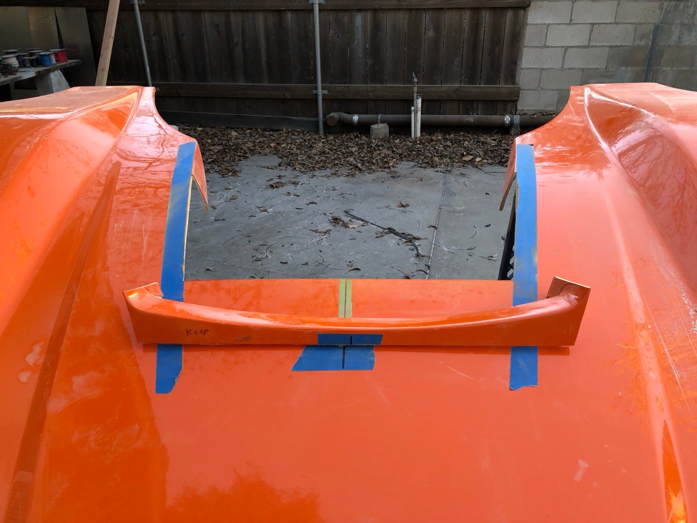
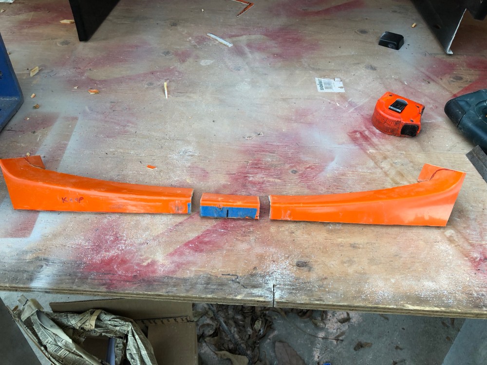
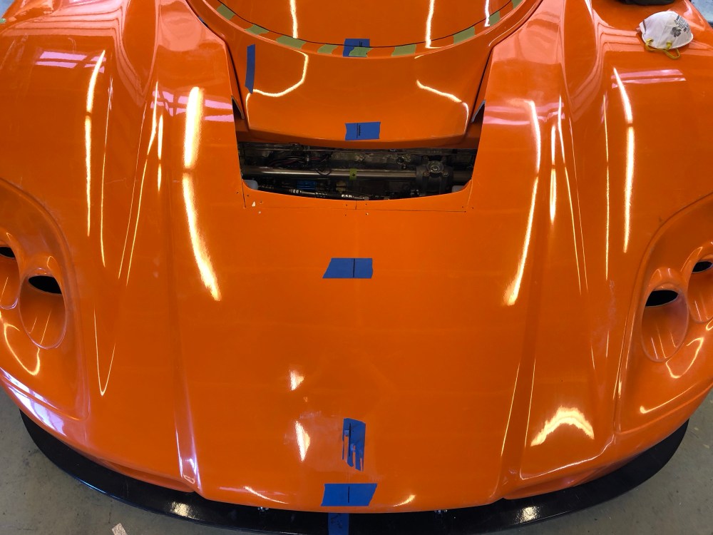
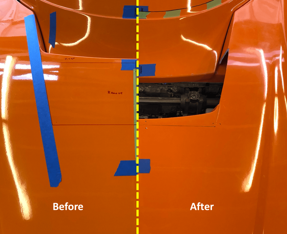
Time to patch that section I cut out …
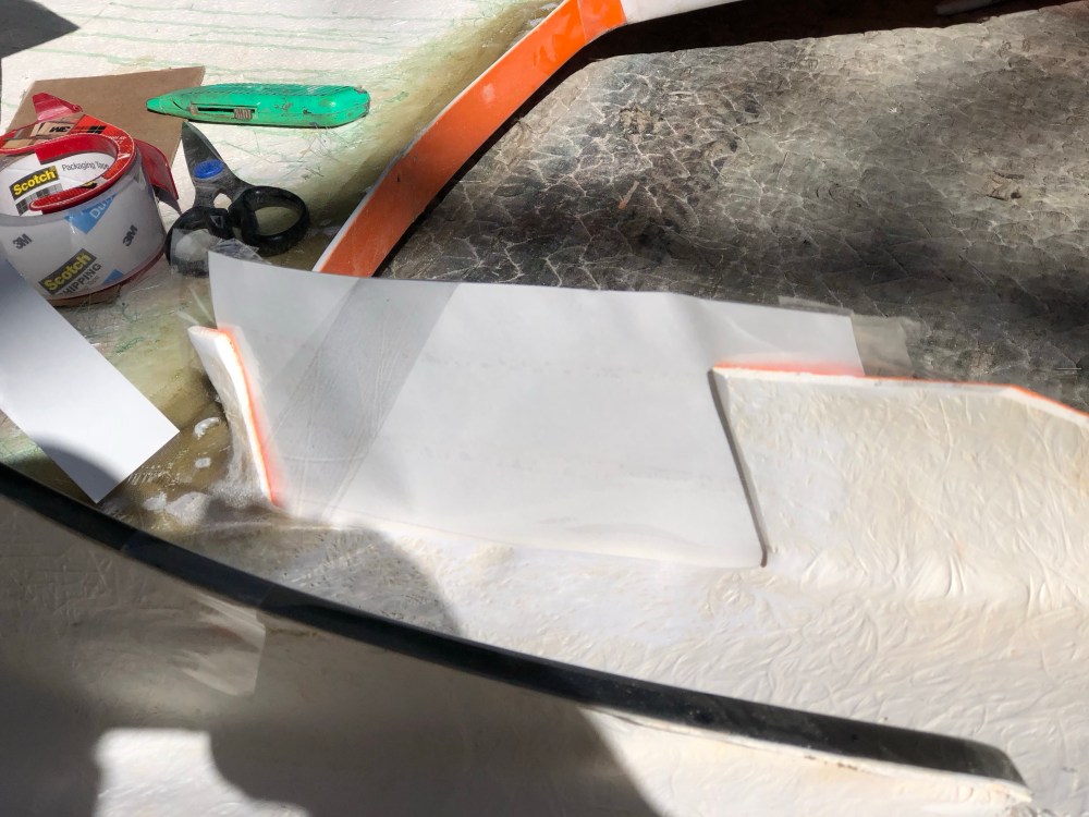
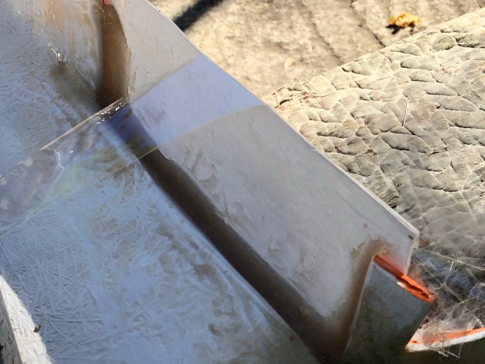
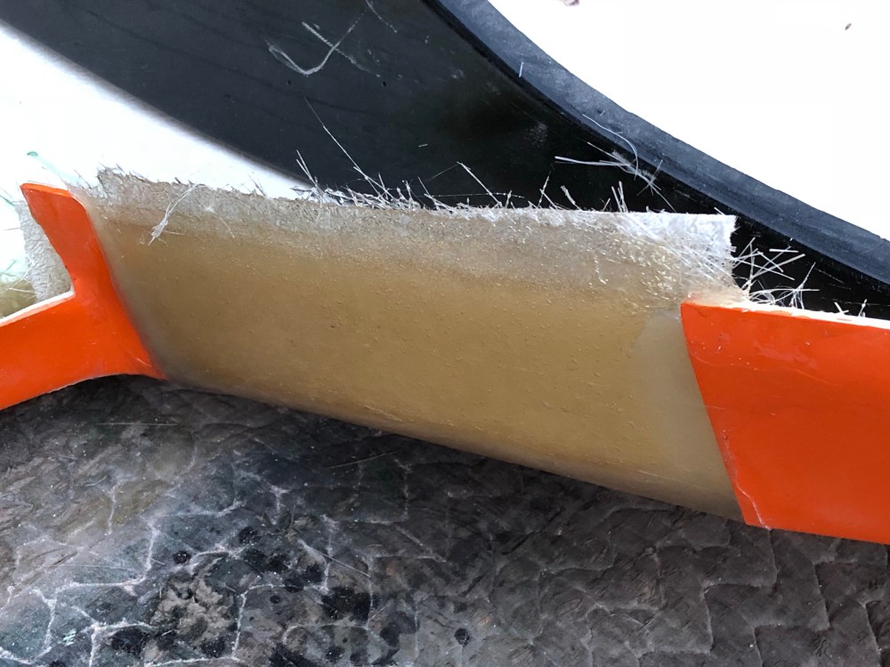
As I said, I screwed the pooch a bit when I made my cuts and bonded the new radiator exit flange into place. Seems I didn’t remove enough material from the center section and I made the base of the opening too large. This wasn’t obvious to me until I got the hood up to eye level and could sight down the edge of the old opening. (sigh) … signs of an amateur at the helm!
The good thing about my screw up is more material in this area gives added stiffness (needed here) and it was a relatively easy fix.
To do:
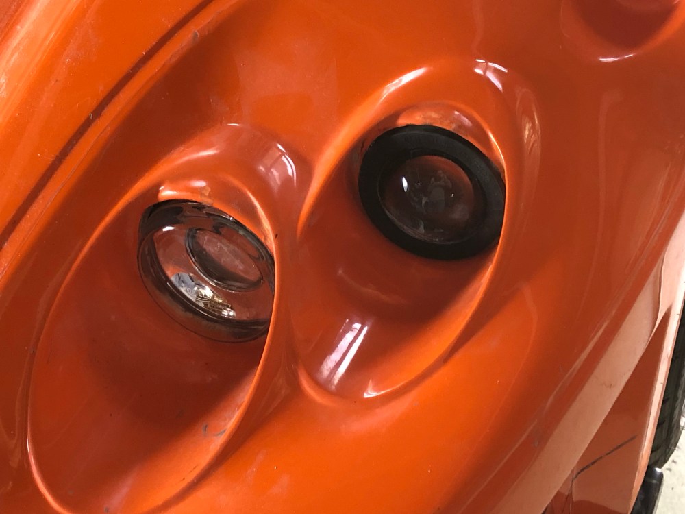
Headlights:
It’s obvious the original mold for the headlights intended for the use of 2 different sized lights. The outboard cutout is better suited to the Hella 60mm projector housings and the inboard cutout for the 90mm housings. The kit comes with 90mm housings for both the high and low beams – I’m not sure why. To get the 90mm headlight to fit in the outboard location, the “eyebrow” needs to be removed to create a large enough hole. The build manual has photos showing what each configuration looks like.
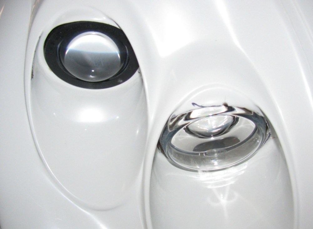
It’s a tight fit and I’m not sure why it bothered me so much, but I really didn’t want to try and cram the 90mm headlight into the outboard location. I ordered a set of 60mm high beam projector housings to use in the outboard holes. Typically (by law) the high beams would be inboard of the low beams. Note also the 60mm high beams have a few hundred lumens LESS output than their 90mm equivalent. I can live with this; I rarely expect to be driving with the high beams on anyway.
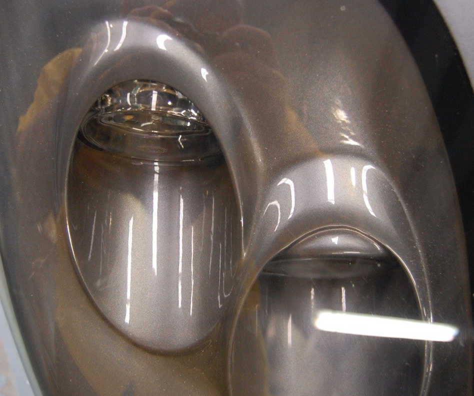
To use the Hella-designed headlight adjusters and get the low beam correctly aligned with the horizon, a small stepped plate needs to be added near the very top-most edge of the cut-out. The low beam must be angled flat with the horizon because there’s an internal shield which blocks light from being aimed up into the eyes of oncoming cars. However, this requires the headlight housing to be oriented such that the required mounting point is aimed right at a location with very little available glass to use for mounting – you can’t simply drill deeper into the glass because you’d poke out into the exterior, hence the small doubler plate shown above.
Mounting the low-beam requires trimming off one of the 4 mounting ears; you want to trim the corner that’s closest (in my setup) to the exterior high beam pocket. Some additional trimming of the housing may be required – my light was butted super close to my bodywork and I had to trim both the body and the headlight housing to get the light somewhat centered within my cutout. Note I ground through all the fiberglass and into the gelcoat in the photo above. Gel coat on its own doesn’t have much strength so I backfilled this with some reinforced resin.
Orientation of the low beam is critical – the “TOP” must be oriented so it’s perfectly vertical with the vehicle when on level ground. The headlight has an internal shield which acts to focus light toward the ground; mounting the light at an angle would “twist” your lights and point them off to the sides. Playing with the adjusters won’t fix this issue. The Hella 90mm mounting screws use a plastic spring loaded insert which gets installed into the mounting plates. A ball-end screw is then inserted into the plastic insert. This assembly is first installed into your mount; then the headlight housing passes through the aft end of the screw and gets twisted onto the housing assembly, locking it into place. Aiming of the headlight is performed from behind the housings.
The 60mm Hella high beam projectors I purchased use an odd-ball mounting scheme. The supplied mounting screws are meant to self-tap into the housing from the FRONT of the vehicle. This means any aiming of the high beam needs to be performed from in front of the vehicle. Issues with this arrangement include ugly fasteners visible from the front which are inaccessible if you plan to run the clear closeout covers. Orientation of the high beam is less critical; it’s a projector light which does not run an internal shield – so there’s no “UP” orientation. Here, it’s primarily aiming that’s critical. As with the low beam, only 3 fasteners can be used for mounting (unless you’ve added some extra material for a 4th). I oriented my high beam such that 2 of the 3 were aligned horizontally with the 3rd below. Using the two aligned screws let’s you set your left/right aiming while the 3rd allows you to independently adjust up/down. This same aiming scheme is used for the low beams.
To ensure I had the lights mounted correctly I once again used my trusty Dewalt laser level to draw horizontal and vertical lines while I drilled the required mounting holes. Of course the front clam needs to be level with the horizon when performing this procedure.

Wheel wells:
Uuungh.
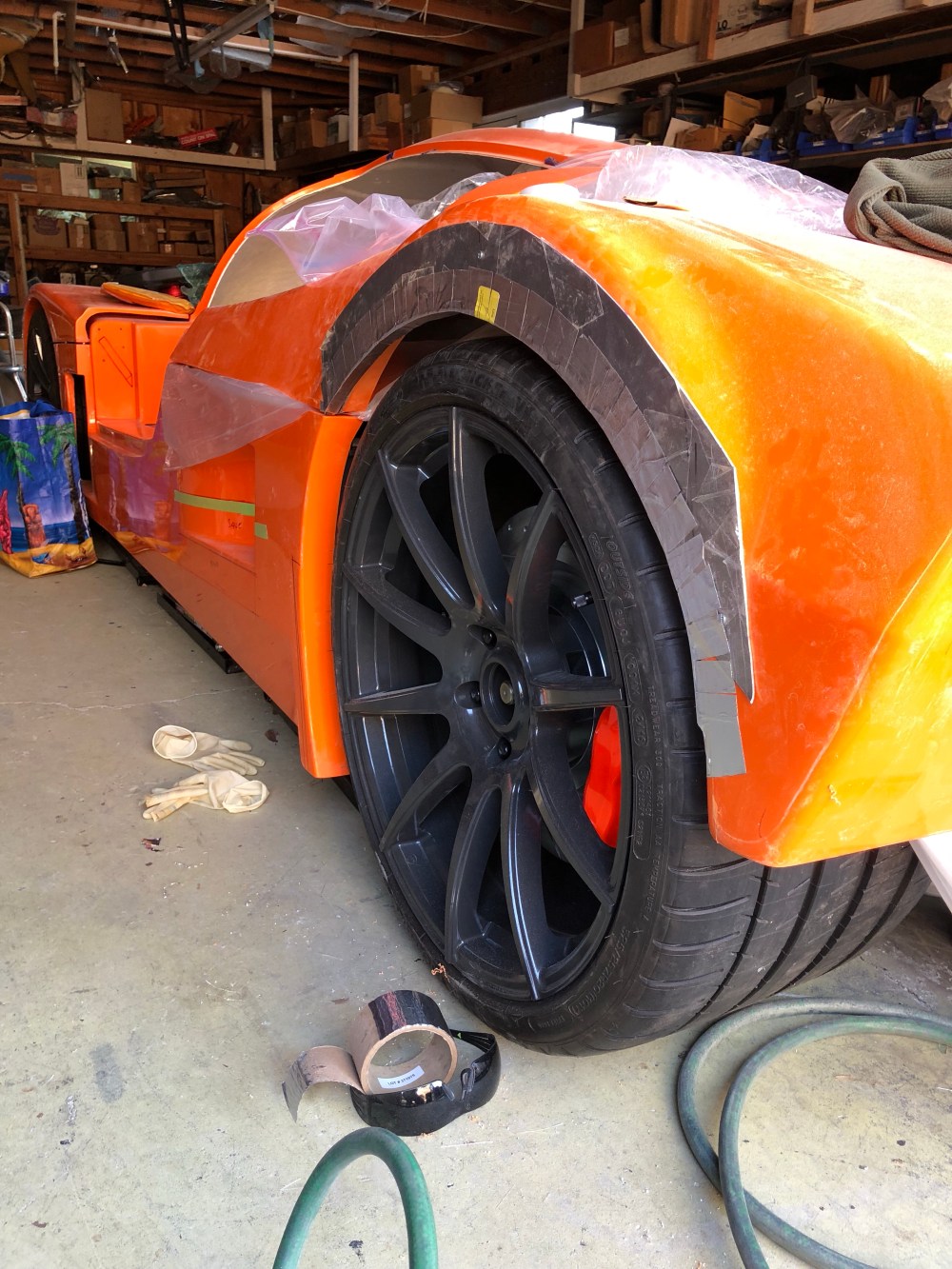
With an intro like that you know this isn’t a fun subject. There are several issues with the wheel wells – take the following as my opinion only.
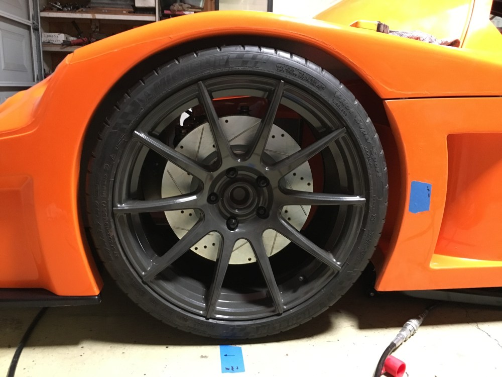
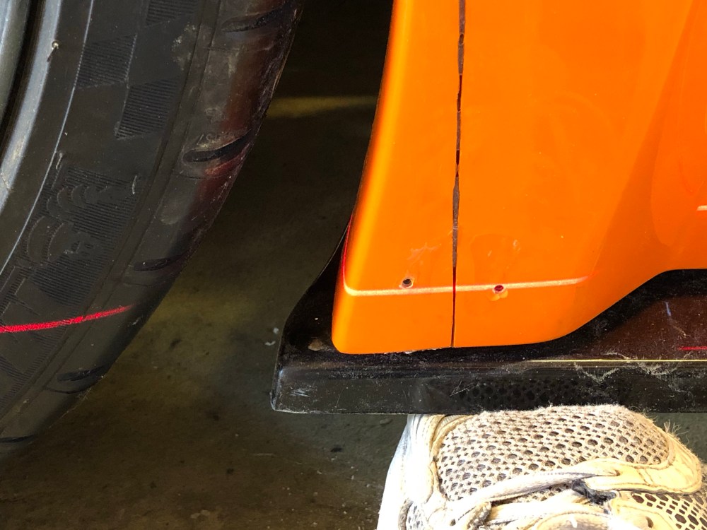
- Both the front and rear wheel wells have too much angular wrap around the wheels. If trying to do a wheel change it’s almost mandatory to have a jack supporting the suspension while the car is elevated otherwise a portion of the tire contacts, or comes very close to contacting, a portion of the wheel well. If that happens the wheel becomes locked in, between the wheel well and a wheel stud. To alleviate, you jack the suspension up enough to clear the interference, then very slowly and carefully pull the wheel away from the rotor. It’s kind of like a game of Operation – you need to suspend the wheel perfectly centered otherwise you risk damaging the wheel or your preciously powder coated brake calipers.
- If trying to build a car with an aesthetically pleasing stance you need to run fairly low ride height. During my initial suspension alignment I set both the front and rear at 4″; I believe this is too low for the street.
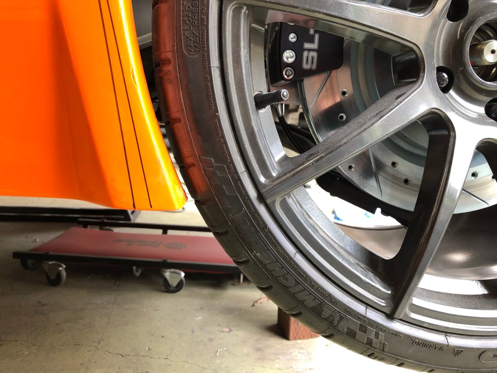
- FRONT RIDE HEIGHT: 4″ front ride height leaves very little clearance between the wheel and top edge of the wheel well. I believe under hard braking the front wheel will dive enough to make contact with the wheel well. At 1-deg negative camber there’s not enough camber gain to tuck the tire before it makes contact. As it stands, I’m already running the front track at its narrowest possible setting. All front LCA heim joints are fully spun into the LCAs and the lower ball joints are non-adjustable. To tuck my front tires I need to run extreme negative static camber, or revise the wheel wells by making them wider.
- As a compromise I’m planning to run a 4.5″ front ride height, hoping it’ll be enough to avoid wheel rub.
- REAR RIDE HEIGHT: 4″ rear ride height is simply too low, especially on a car running a rear wing. I believe street tails are advertised to generate a fair amount of downforce as well – so this may also be true for street tail cars. The build manual recommends a 1″ negative rake angle. So for a car running a 4″ front ride height the recommended rear ride height is 5″. The negative rake does a few things:
- Improved whole-vehicle aerodynamics. The entire car acts like a wedge and a negative rake turns the whole underside of the car into a diffuser surface. With a positive rake that would promote lift.
- As vehicle speed increases rear downforce will outpace front downforce gain. So as speed increases, vehicle angle of attack will shift positive. Insufficient static rake angle will cause front end vehicle lift if it’s not enough to compensate for the angle change due to rear wing downforce gain.
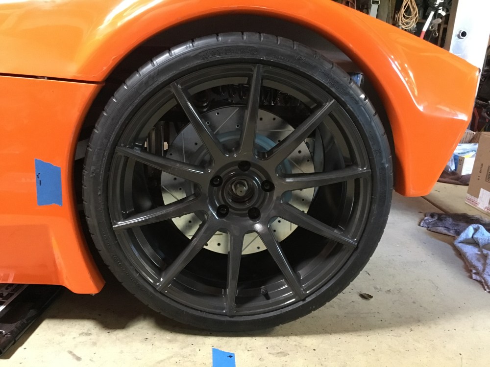
- Since I’ve settled on 4.5″ front ride height, that sets my rear at 5.5″. at 5.5″ rear ride height the wheel gap looks hideous. I can almost put my fist in between the top of the tire and the wheel well. The wheel well contour becomes so mismatched with the wheel that a nice stance is impossible.
- FRONT RIDE HEIGHT: 4″ front ride height leaves very little clearance between the wheel and top edge of the wheel well. I believe under hard braking the front wheel will dive enough to make contact with the wheel well. At 1-deg negative camber there’s not enough camber gain to tuck the tire before it makes contact. As it stands, I’m already running the front track at its narrowest possible setting. All front LCA heim joints are fully spun into the LCAs and the lower ball joints are non-adjustable. To tuck my front tires I need to run extreme negative static camber, or revise the wheel wells by making them wider.
Basically – the wheel wells need a fair bit of massaging, the front less so.
The front end wheel well issue appears to be universal. The rear wheel well misalignment/non-concentricity may be a race tail only issue. I’ve seen several (many) race tail cars built with wheel wells that are well centered with the wheel. It also appears many of these builders have opted to push rear ride height down to achieve this improved stance at the sacrifice of inducing negative rake angle – I’m basing this purely on fuzzy photos I’ve seen on the internet, not based on first-hand measurements so take what I type with a grain of salt.
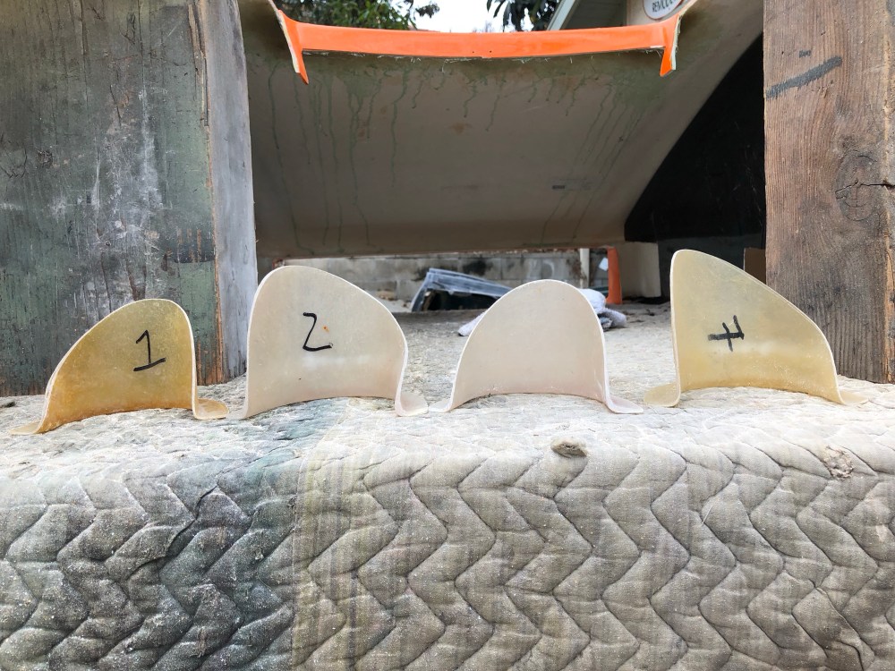
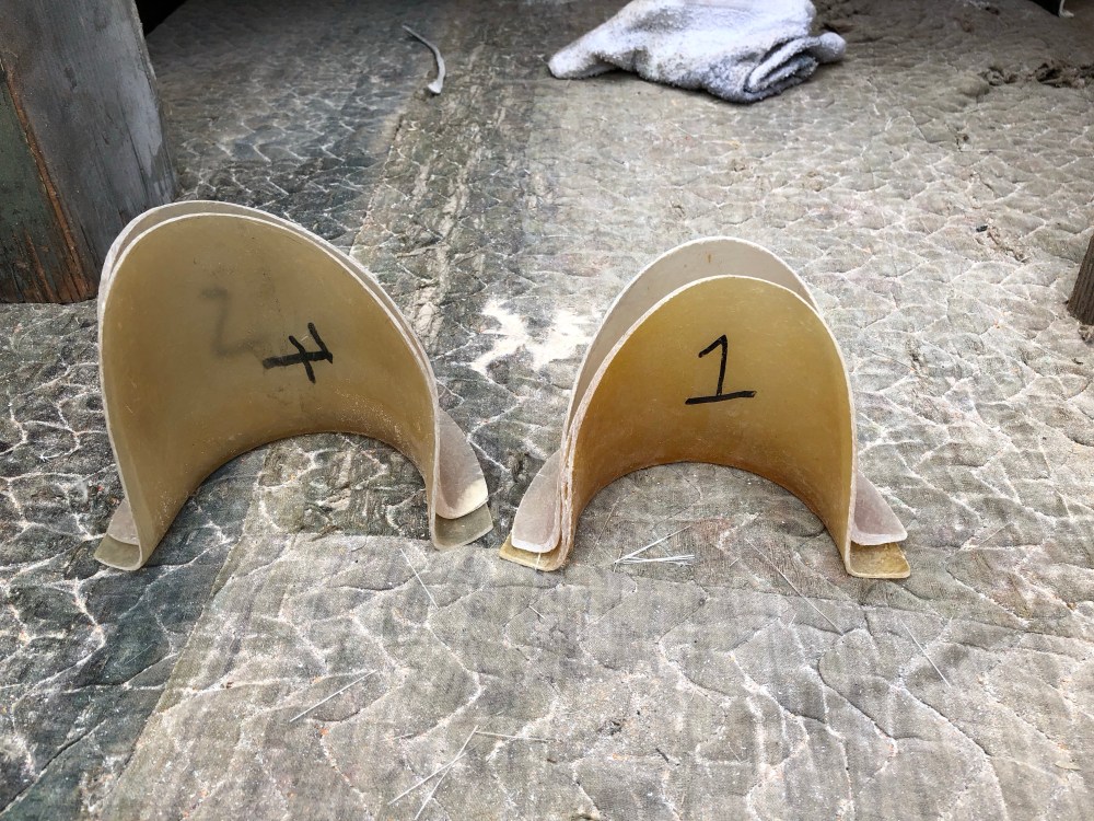
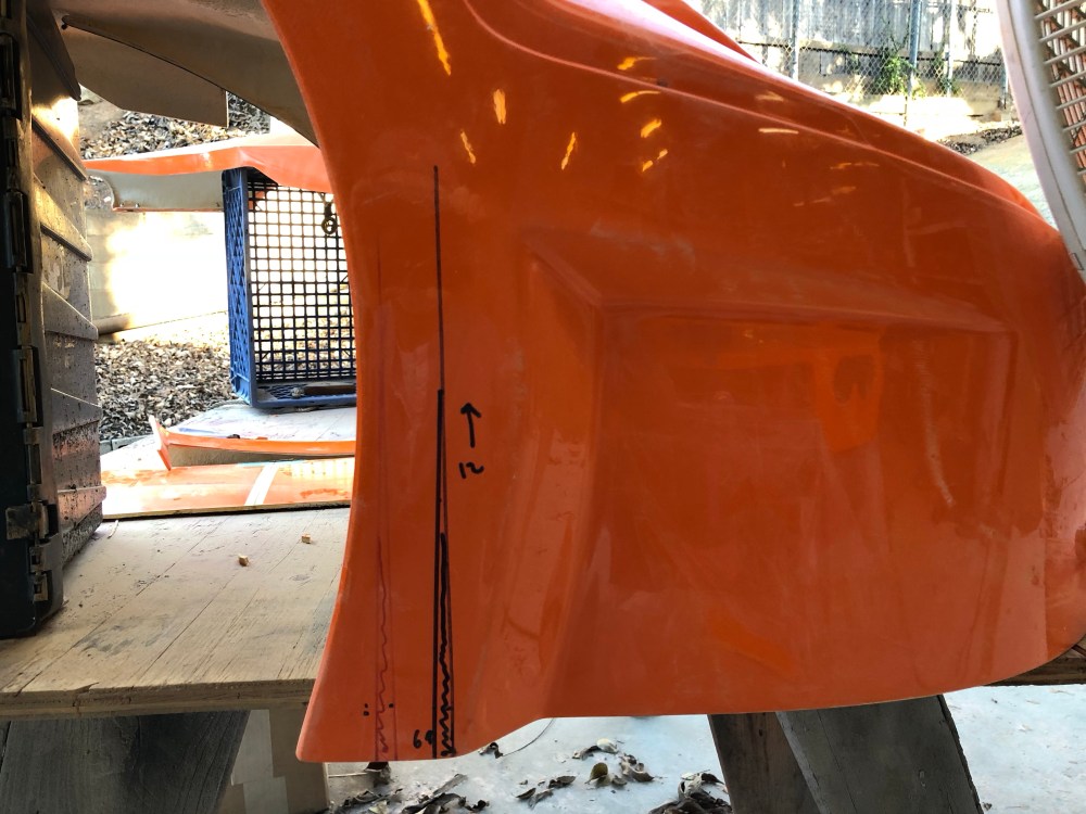
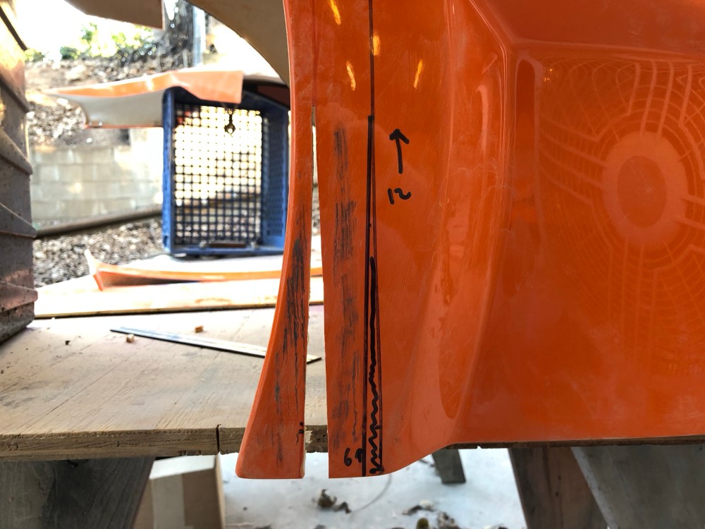
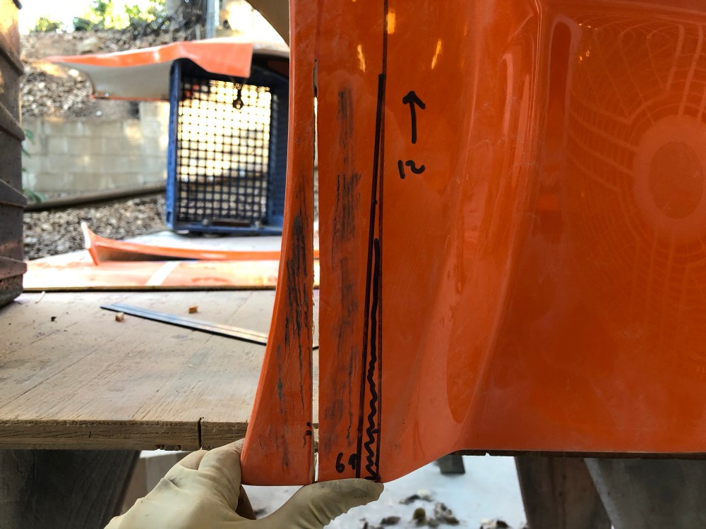
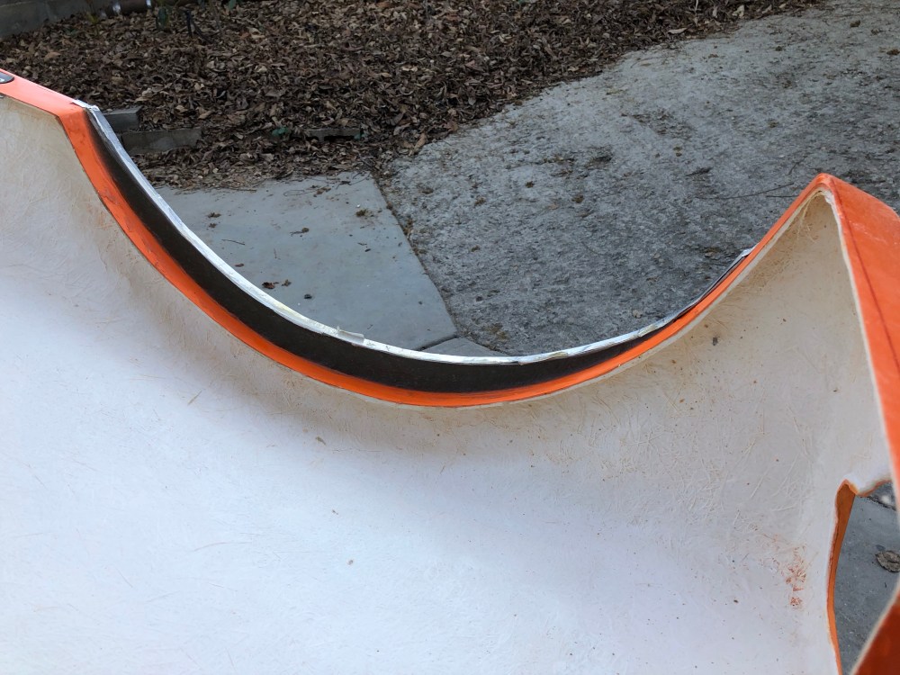
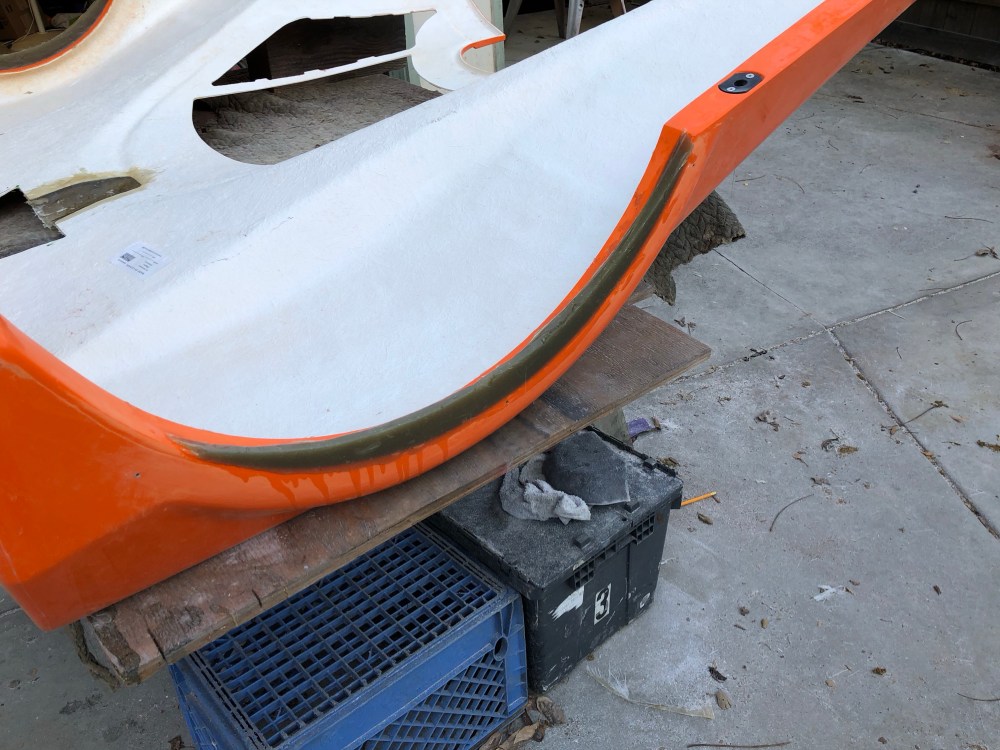
Recontouring the wheel wells:
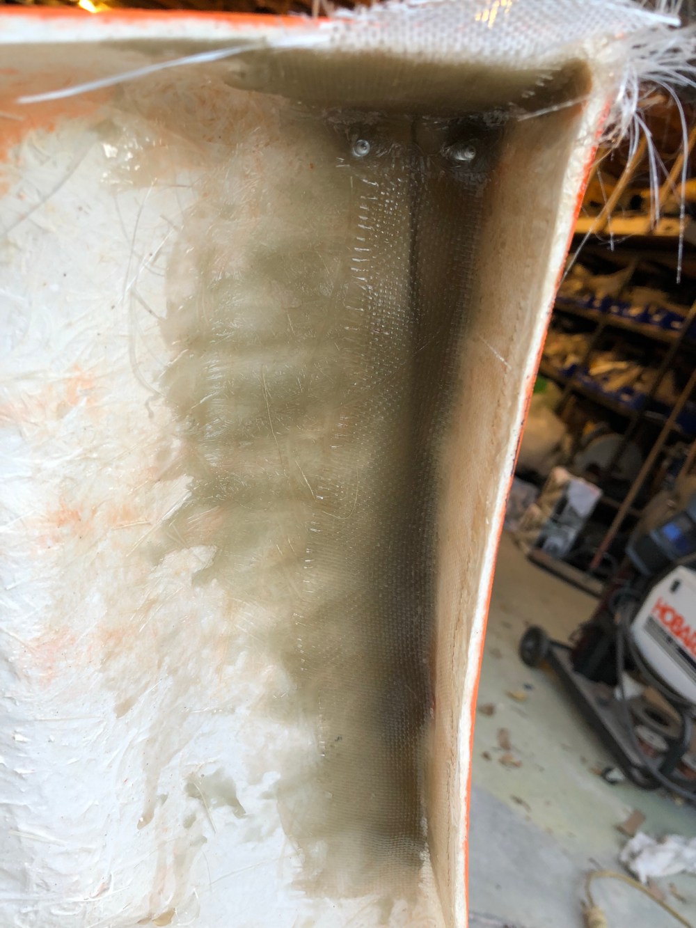
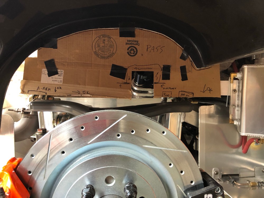
Credit once again goes to HJones for the inspiration on this modification. To reduce the amount of wheel well wrap at the front I took a small triangular wedge of material out of the front clam, just forward of the wheel well. With this material removed, I then squeezed the pieces together and glassed them in place. I shifted the lower edge forward by 0.5″ and stopped the transition where the arch goes vertical, about 12″ above the lower edge.
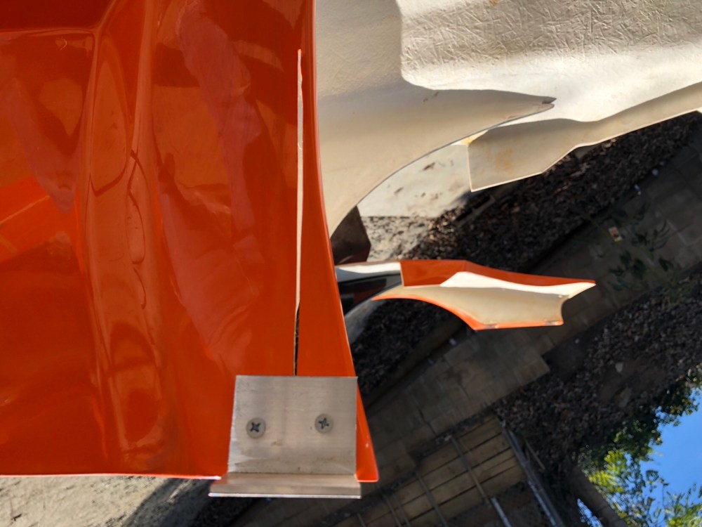
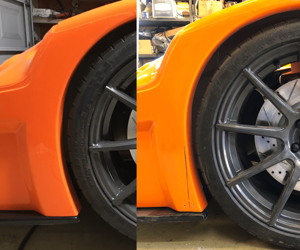
Other than the lower forward edge of the front wheel well, there’s not much more needed.
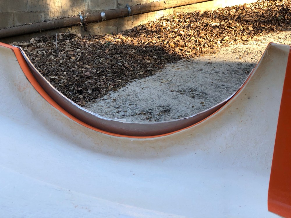
The story is less cheerful when it comes to the rear.
I’ll modify the lower forward edge of the contour as I did with the front. Since this portion of the wheel well is part of the center I haven’t gotten to this modification yet.
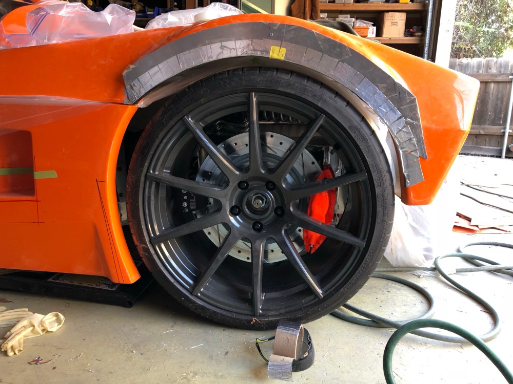
After looking at this picture more and seeing how lopsided the new contour looks, I’ve decided I’m just going to recontour the entire wheel well – the goal is to make it as concentric as I can to the wheel with a rear ride height of 5.5″.
As I said, Uuungh …
To do:
- Complete recontour of rear wheel arches.
- Complete fitting and installation of wheel well liners.
Wheel well liners:
I ordered the optional wheel well liner kit because I didn’t want road debris being flung everywhere. It’s less critical in the front. It’s easy enough to build a closeout to protect the headlight assemblies and any exposed areas of the radiator box. Otherwise there isn’t anything special about the factory offering.
In the rear, there’s a lot more at stake. Unless you build your own engine closeout plates the engine is highly susceptible to road debris. Additionally, if you’ve placed oil/trans coolers near the side vents these are in direct line of fire to rear tire road debris.

I goofed a bit with where I mounted my oil cooler – it’s too close to the rear wheel contour. The factory produced liner which installs at this location needs more room than I gave it – so it doesn’t fit. I’ll need to make my own panel.
As with the rear, the front wheel well liners need to be opened up more than the molded cut lines to provide sufficient access for the headlights. In this case the headlights can pass through just fine – but there isn’t adequate line of sight access to get to the headlight adjusters.
My passenger side liner fits decently well without significant trimming. The driver side wasn’t as eager to play ball. It’s about 0.5″ too wide.
To do:
- Complete front wheel liner install.
- Complete rear wheel liner install – holding off on doing this until I get the rear clam hinge point installed.
- Fabricate rear lower liners.
Yeesh, that’s a lot of fiberglassing work I didn’t anticipate doing! I’ve only really focused on the front and rear clams; the spider modifications will proceed once I get the body off the car once again before I start closing out the interior…
… which leads me into the next part of this update!
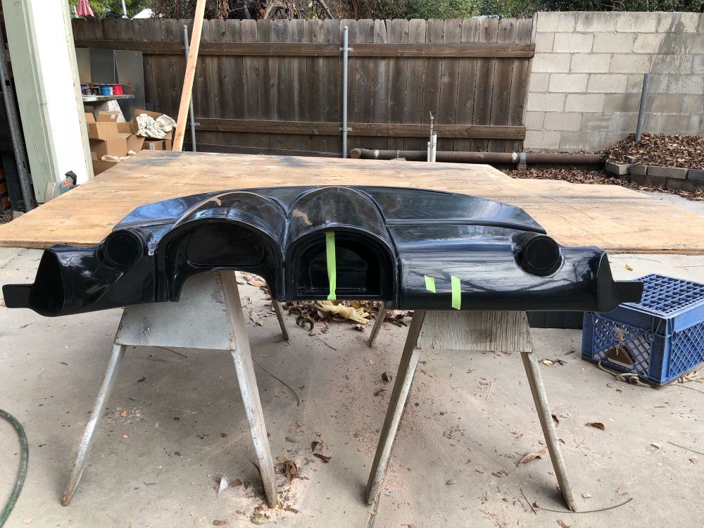
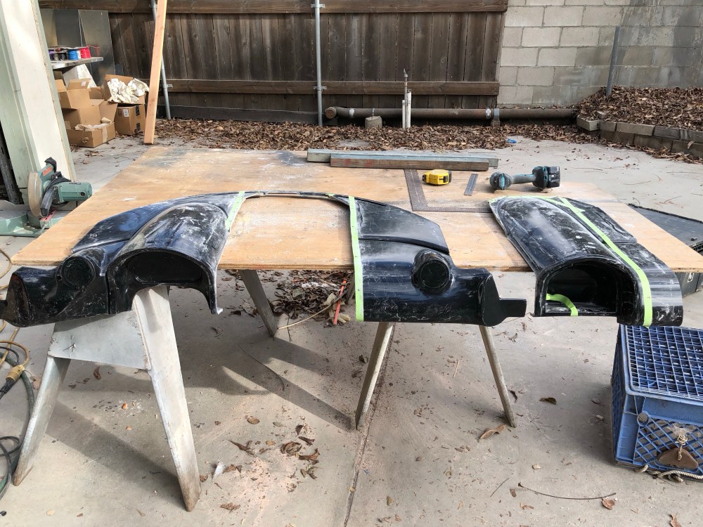
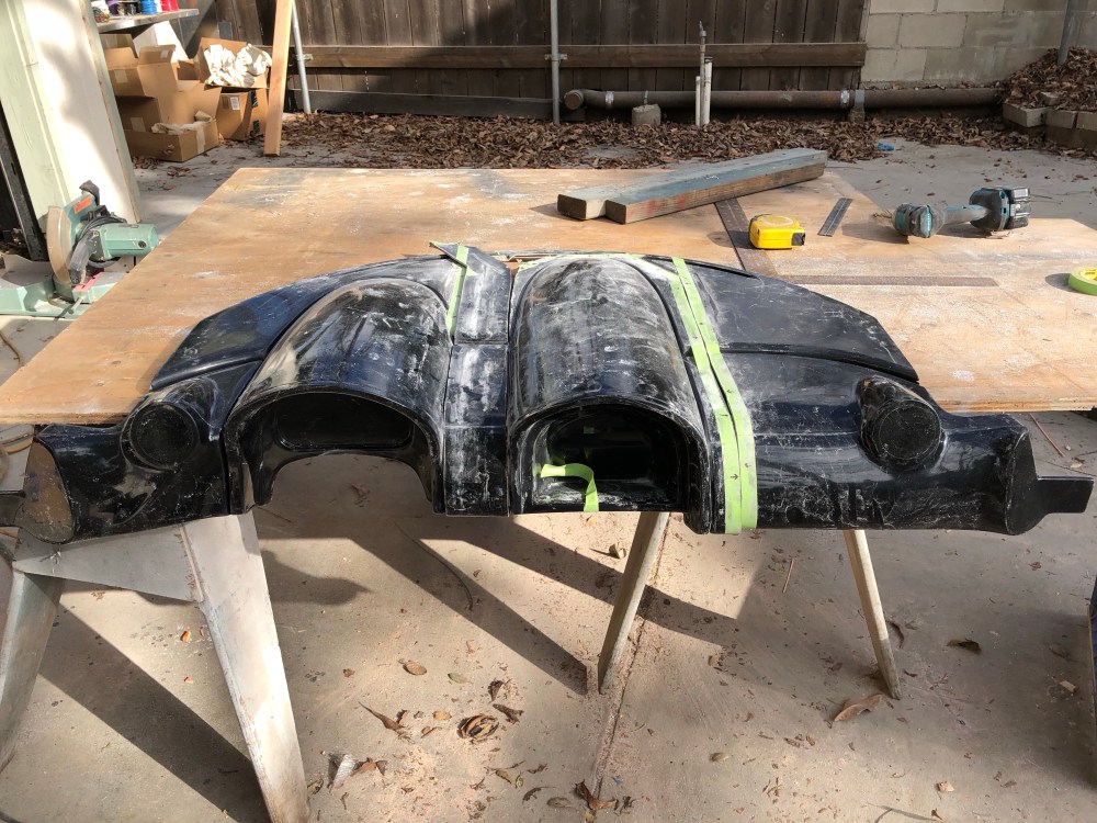
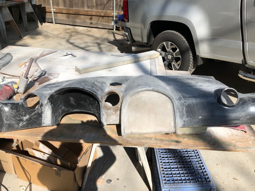
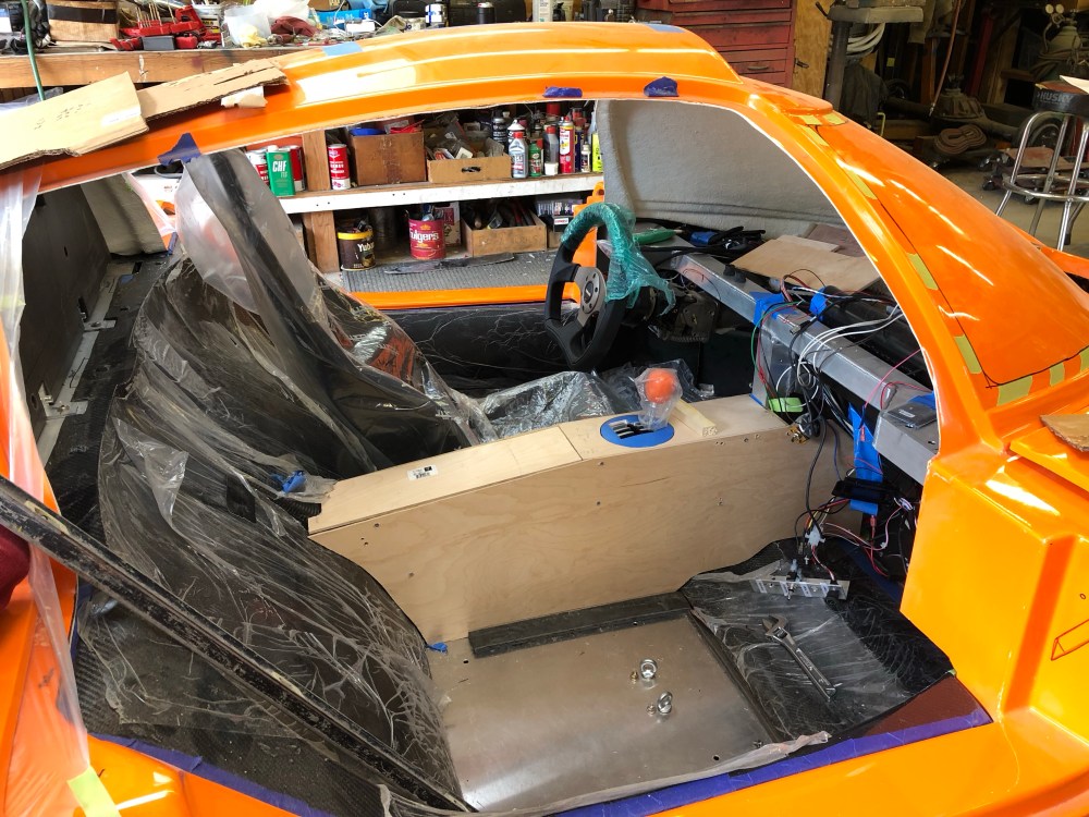
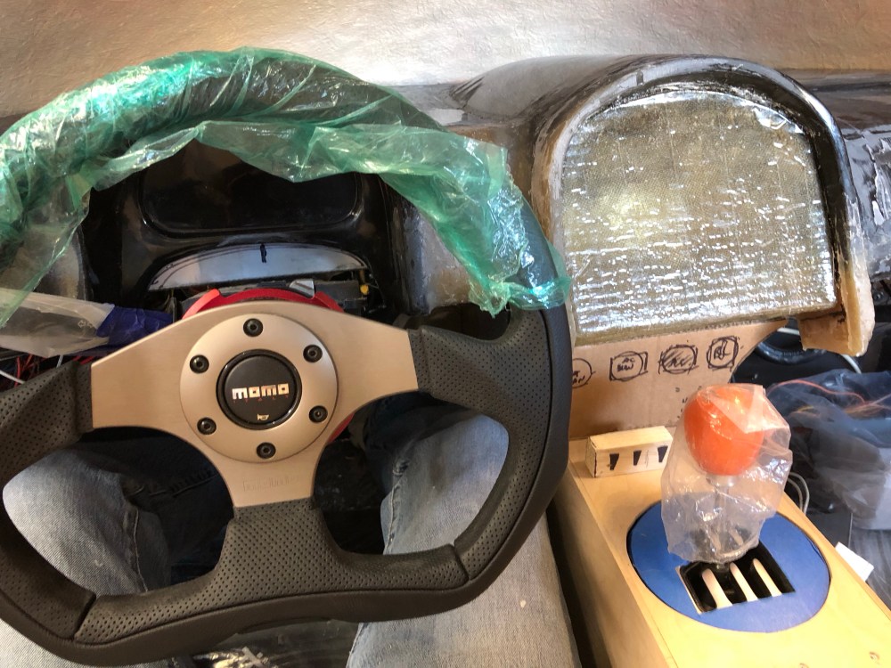
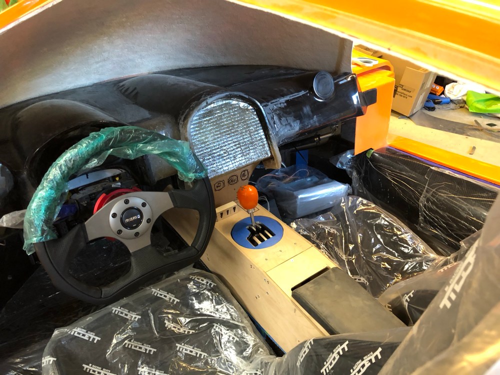
Dash & center console:
The dash panel is pretty nice as-delivered, certainly much nicer than anything I could fab up on my own. Unfortunately it too needs a fair bit of work.
Spacing between the driver and center binnacles is too close. The steering wheel obscures half of the center binnacle, making it almost unusable as a location for a radio/GPS display – at least for me. Since I’m relatively short it means my seating position puts me up close to the wheel making it more difficult to get a good view of the center binnacle. This is less of an issue if you’ve got long arms and can push your head further away from the steering wheel.


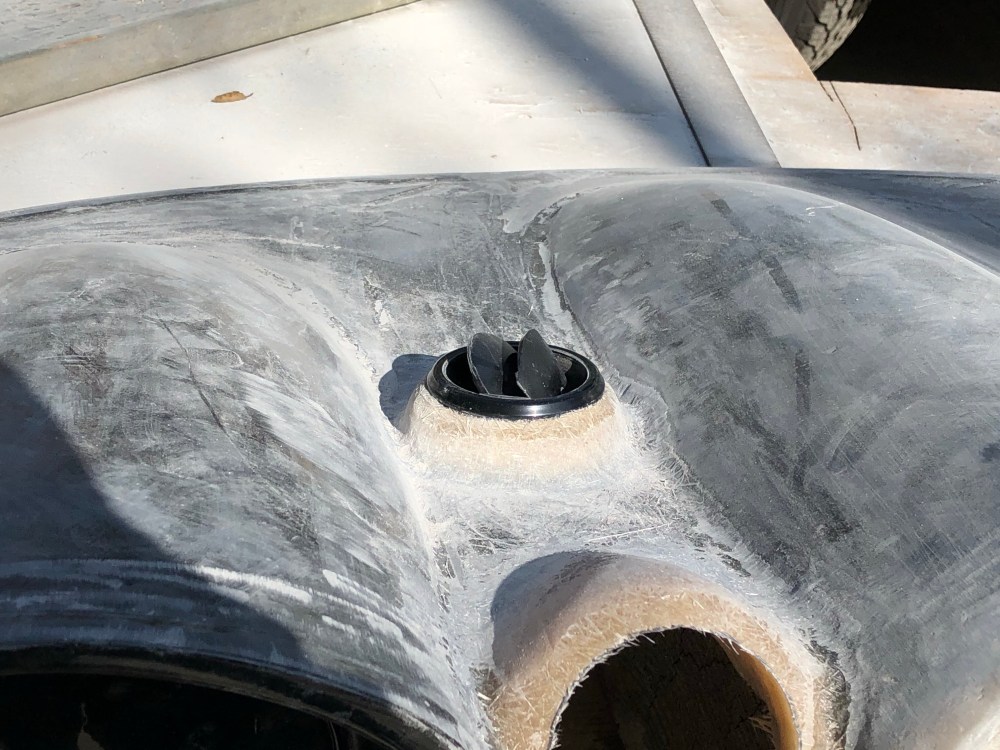
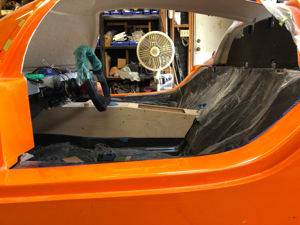
The front window defroster design isn’t great – to make this area functional you need to use the large anchor shaped manifold to transport air from the fan unit towards the defroster vents at the forward location of the dash. The defroster passage is open at all times unless you incorporate some type of diverter – so you’ll be pumping defroster air whenever the fans are blowing. Not a good use of precious air conditioning.
As I showed in an earlier post, I’ve deleted the anchor shaped manifold from my build. To transport airflow from the fans I’m using an assembly of flex ducting and Ys to wherever I need it. I figure a more efficient defroster design is to use a standard aimable vent that can be closed when defrosting is not needed.
Additionally, I wanted to add a third passenger focused vent to improve cooling air directed at the driver. The result of all that is the following …
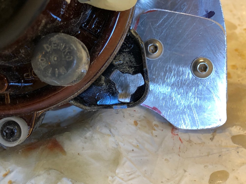
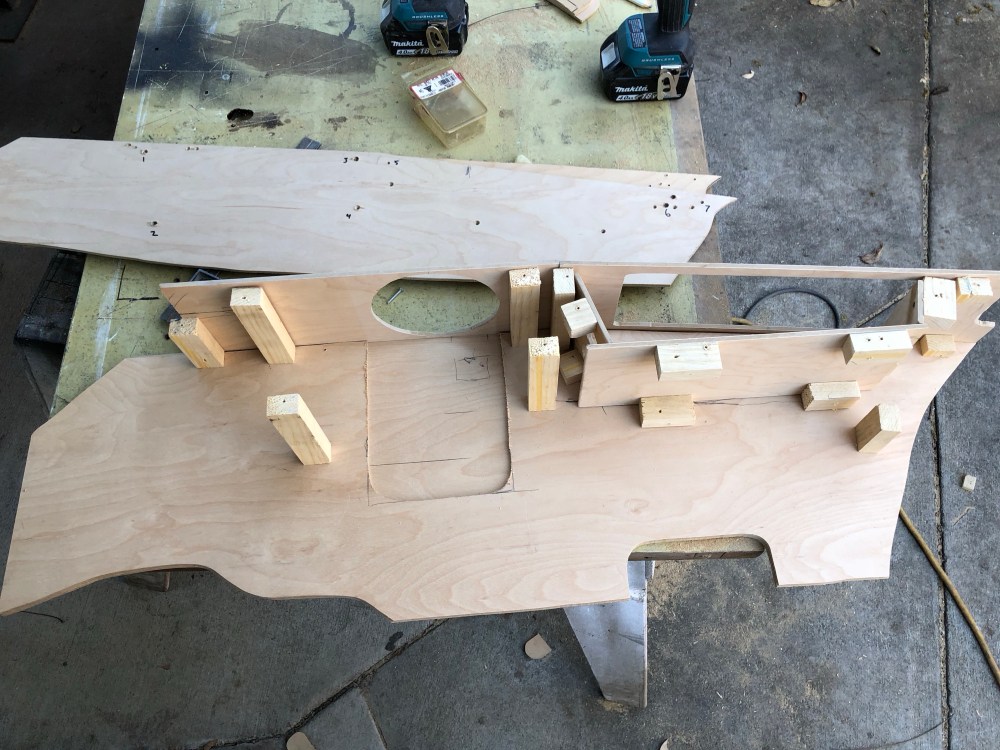
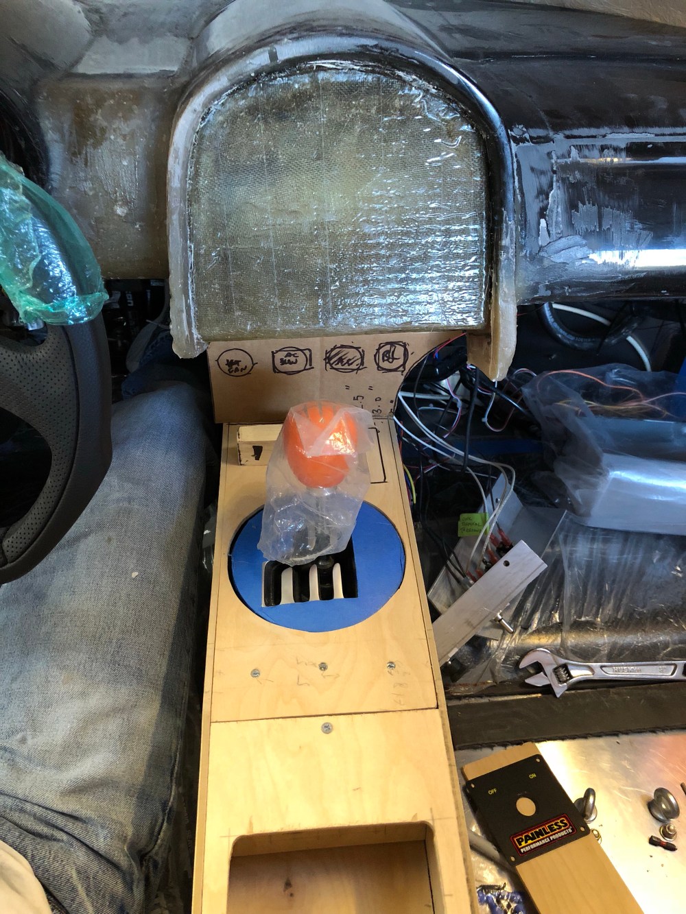
With the dash getting into decent shape it’s time to turn my focus toward the center console. The Audi shifter is too large for the factory-supplied center console. The Audi shifter uses a gated plate which is too wide to be accommodated.
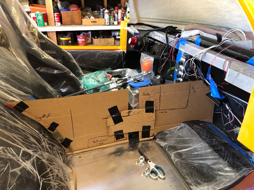
To do:
- Complete dash – figure out what the heck I’m going to cover it in. Bouncing back and forth between Alsa soft touch or fabric. Upholstery shop option seems like a no-go due to availability so either option will have to be slapped together by me.
- Complete center console.
- Make switch and button panels.
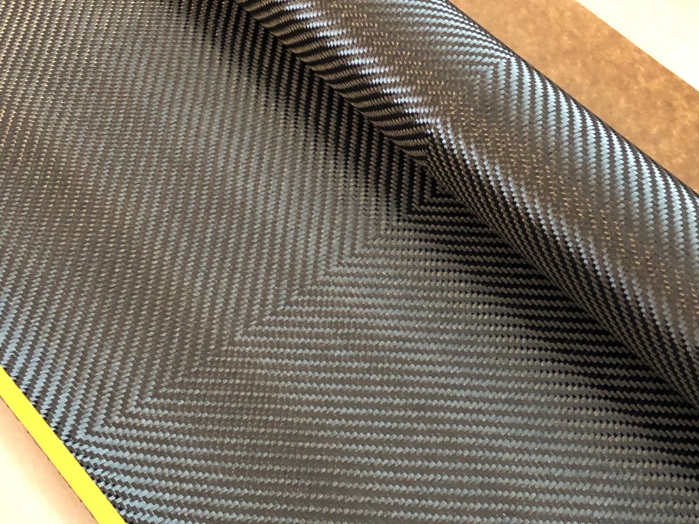
Phew! OK, that’s enough of an update for now. There’s still a TON of work to do to get the body to a point where I can move toward final closeout of the interior and well… everything else! Unfortunately (fortunately?) I’ve been fairly distracted and excited about all this learning I’ve been doing with fiberglass. I’ve decided it’s time to stretch my legs a little and learn some more about working with composites.


3 Comments Add yours