Welp, I didn’t quite make my go-karting goal. Bob was getting ready to pack up for a short trip to Arizona and I was hoping to take a quick spin around the block before he left *just because*.
Bob had volunteered to run the wiring for me after I’d decided to pull the Infinity system from the car. It’s a fairly monumental task and he was able to get me well on my way before having to shove off. With the car still in pieces there wasn’t an opportunity to take that run around the block. Turns out there’s actually *a lot* of stuff to do before we can go-kart the car.
The real setback occurred when we tried to bleed the brakes. I had a heck of a time getting the brake lines sealed up – seemed like it was playing whack-a-mole. As soon as we fixed one leak it just moved on to the next joint. I’d guess about 8/10 joints had some level of leakage, between dripping to moist. After playing the tighten/loosen/tighten/loosen/tighten game enough times and only finding a lot of frustration, I decided to throw in the towel with these stainless lines and replace them all.
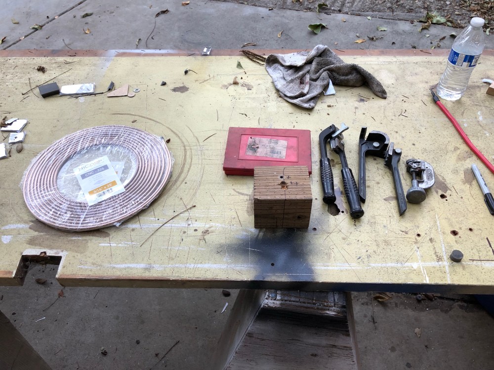
To fix one of the leaks I’d run down to the local Car Quest and picked up a short length of NiCopp brake tubing to make a new jumper. The new line fixed the leak – but as I said, we continued to find more. Anyway, the real discovery was the wonder that is NiCopp (or Cunifer for Cu/Ni/Fer or Copper/Nickel/Iron). NiCopp is the brand name for one of the bigger manufacturers of the stuff – it’s used as the OEM brake line for Porsche and other European manufacturers. Since it’s primarily copper based the lines are relatively soft – so soft you can easily work it with just your hands. It’s also super corrosion resistant, guaranteed to never rust. Best of all, it’s a lot more consistent and easier to get a leak-tight joint.
I ordered 2 25′ rolls of NiCopp which was just enough to re-do the entire car. Otherwise, tools were fairly basic – harbor freight style flaring tool, tube cutter, tube bender, tape measure, and a sharpie. For those longer runs it’s measure three times, give yourself extra, then give yourself a little more before cutting.
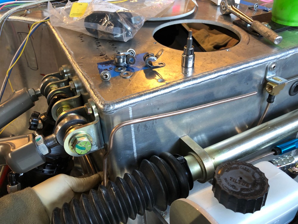
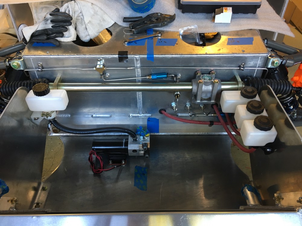
Since I was re-making all the hard lines this gave me an opportunity to address some of the things about the factory lines that were making my OCD tendencies twitch. The first issue I had was my rear brake and clutch lines lay right on top of each other by the front suspension. No amount of tweaking I could do would get them separated enough to make me happy, so I had just kind of lived with it and moved on. I may have secretly been wanting to re-do the lines just so I could fix this …
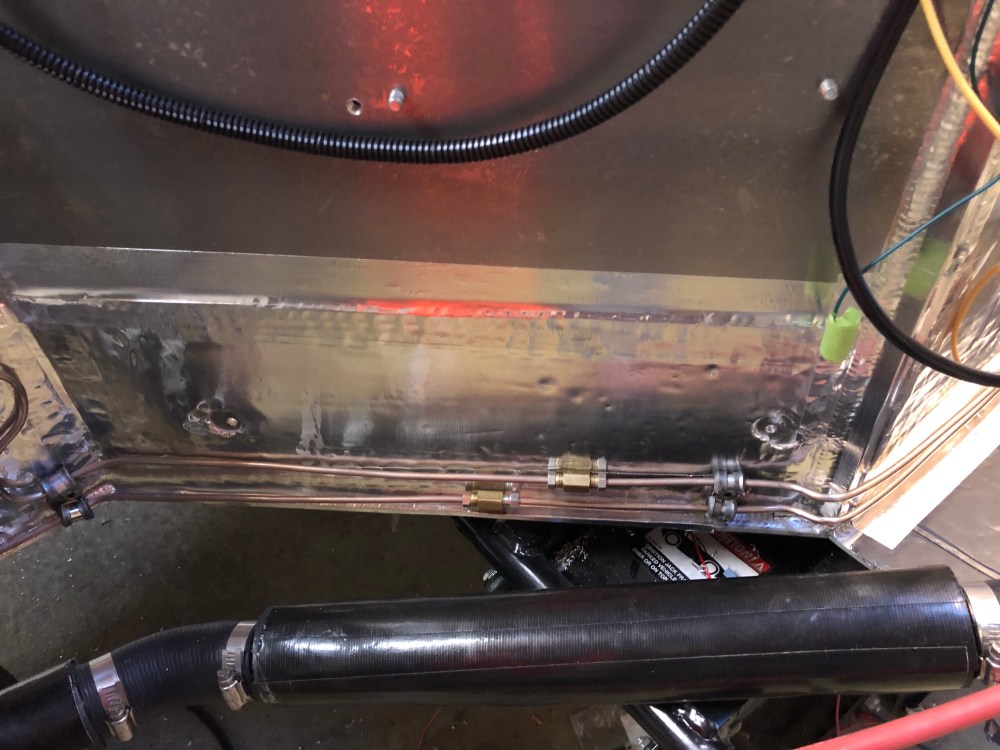
The new lines locate all joints in areas that can be visually assessed for dripping leaks and physically accessed to check for weepers. I believe I’ve also designed them such that if any length needs to be replaced, it can be done so with the spider section still mounted to the chassis.


The second area of concern with the factory lines was how the rear brake and clutch lines have a union along the left pod area, mid body. If there were a leak here you wouldn’t know it until you’d lost enough fluid it became dramatic or you got lucky and it made its way out from the center of the body.

Not a real biggie but I wasn’t super jazzed about the area in front of the foot box either. The rear residual valve is buried and the line coming off the brake pressure switch could be better – don’t like the up/down/up run in it.

I also discovered my residual valves are labeled incorrectly. The arrow is supposed to point in the direction of flow. In my case BOTH valves have arrows going in the wrong direction. On our initial attempt at bleeding the brakes we’d done a decent job of the rears (apart from the weepers which remained after running around and tightening everything that really leaked). We next moved onto the fronts – and that’s when I discovered I was getting NO flow from the front master cylinder. I scratched my head for a while before looking at the residual valve’s orientation and saw it was reversed from the rear valve. Ah-ha! The valve was installed backwards …
Then I pulled the front residual valve and saw it had in fact been installed per the label, with arrow pointing in the direction of flow. Hmm… I blew into the valve and sure enough, I could blow into it from the opposite direction, but I couldn’t get any flow in the opposite. While I was redoing all the lines I pulled the rear residual valve and it also is incorrectly identified. So the valve was indeed installed backwards, but correctly per the manufacturer’s labeling.
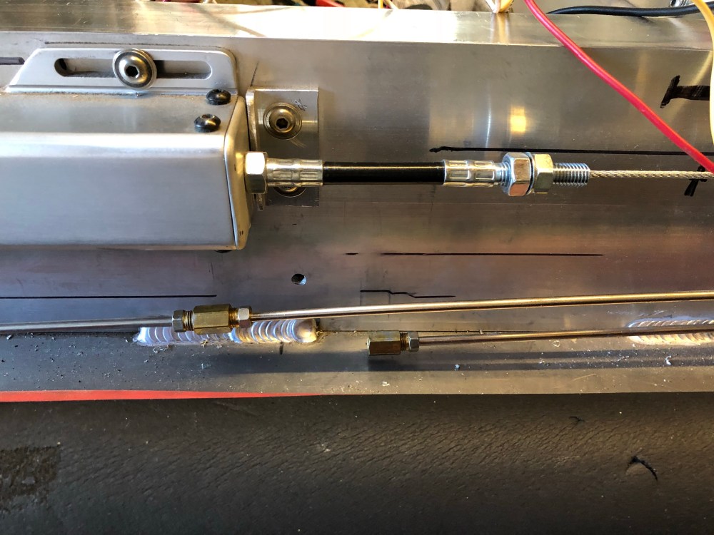
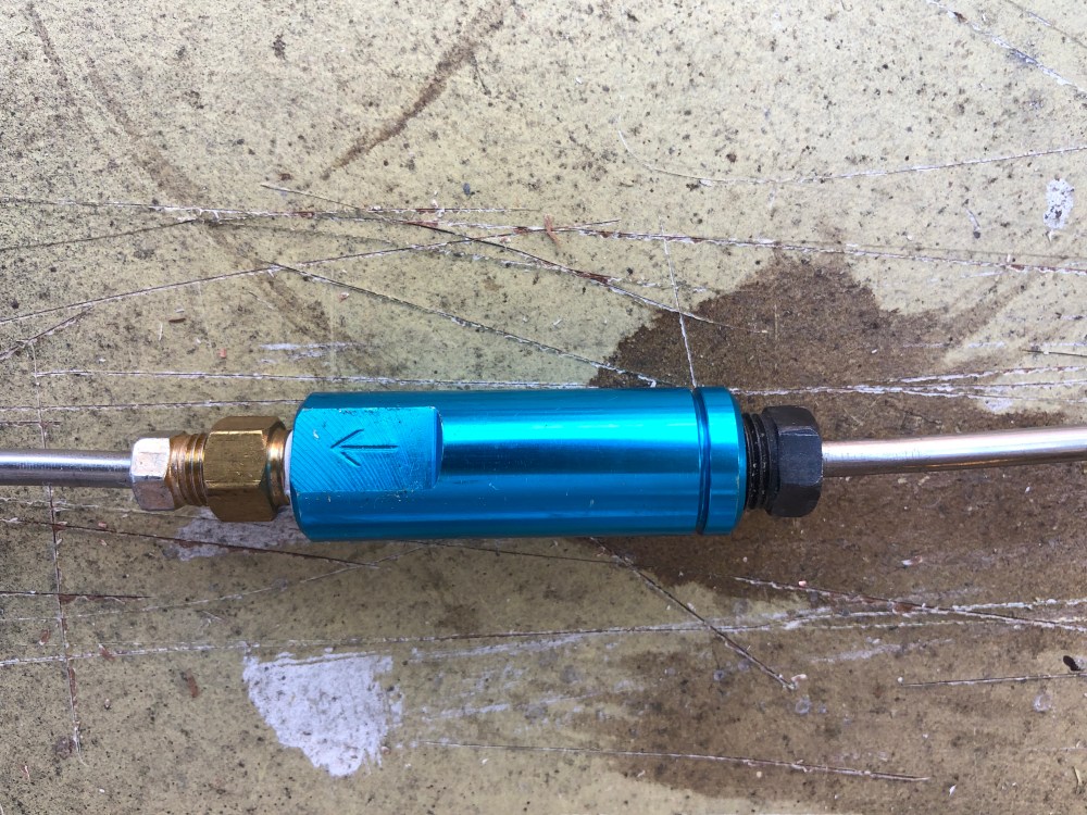
Note to others – take a look at your valves and make sure they’re BOTH installed in the “correct” orientation. The correct orientation, per the photo below, is flow going from left to right. The line on the left goes from a 3/16″ inverted flare fitting (using 3/8-24 threads) to an NPT adapter. To the right, the residual valve uses a goofy 1/4″ inverted flare fitting but uses a 3/16″ line (so 7/16-24 threads but with a hole for a 3/16″ line). I could NOT find any of these 3/16″ / 1/4″ hybrid fittings at any of my local parts stores.
This is the first time I’ve heard about incorrectly labeled valves. I’ve gone through other build photos and it seems other builders have figured this out – but I haven’t seen any discussion of this error in any of the build logs. I’m surprised there hasn’t been more attention paid to this oversight! I did post of my findings to the GT40s website (see my build thread) but the only feedback I’ve gotten is these valves are “junk” but not much more to go on. Historically these valves used to ship separate and builders would try to remove the brass fittings installed in them so they could be used on the car – for some reason it seemed a lot of folks were damaging/breaking the brass fittings and ruining the residual valves during the removal process. The popular option seems to be replacing these valves with Wilwood equivalents. I’m starting to approach “replacement PTSD” – throughout the project I’ve been replacing factory parts with other components and I’m getting weary of doing so (not to mention poorer!). Hence, I plan to stick with these residual valves until they functionally appear to be defective. I’ve plumbed and re-located the valves so if I need to replace them they’ll be accessible and I won’t need to make a large section of line to accommodate the new valve (assuming it will be a different length).
Fast forward through 2.5 days of staring at the chassis and bending brake lines and …
SUCCESS! The brakes are now bled and there are zero leaks!
What a great experience, I was feeling pretty kicked down about not being able to get the stainless lines to seal – just didn’t seem to have the touch I guess. While I was pulling the steel parts off the car I did find one cracked flare, the others just didn’t seem to get a good seat. Getting the new lines bent, installed, improved upon, and leak free really gives me a high, more motivation and confidence.

With the brake and clutch lines now in check it was time to turn my attention back to wiring.
A slight segue before jumping into the wiring. This next bit sits on top of the footbox, next to a lot of wiring, and it got me thinking I should talk about this …
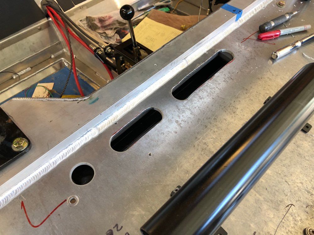
I don’t like the “boat anchor” air conditioning/ventilation manifold system that’s supplied by the factory. I think it’s a pretty good way to lose cooling pressure and efficiency. To try and maximize air conditioning performance I wanted to decrease the pressure loss between the evap manifold and the distribution system above the footbox. The chassis comes pre-drilled with ~7 holes along the front of the passenger side; these holes line up with where the evap manifold sits, assuming you were able to suss out a way to install the box in its intended location. The very last hole is positioned too far to line up with the evap box – so it’ll never be used. I connected the holes and turned them into larger slots, keeping one rib in the name of chassis stiffness.
In place of the anchor manifold, I had Bob fabricate a short section of 2.5″ tube with a collector welded to its base. This collector mates up with the slotted holes; I can then attach 2.5″ ducting to connect this new collector to my various vents located around the cockpit. For the defroster, I plan to use a single vent that points up toward the windshield. When not in use, I can simply close the vent and keep all the air coming towards the passenger compartment.
The goal of this change was to minimize the amount of volume/length of the manifold, thereby preserving system pressure and heating/cooling losses through the distribution system walls.


OK – back to wiring!
Bob had left me in a great spot, all the fuses, fuse boxes, relays, and the alarm system had been installed and mostly wired. I just needed to connect the dots that Bob had left me.


Other items of note – a Dakota Digital GPS (PN GPS-50-2) to feed vehicle speed to the VSS. It seems this addresses an off-throttle stumbling issue. I’m going to try and feed the speed signal to my Aim dash – if I’m not able to use the DD GPS unit for vehicle speed it means I’ll need to fork out another $300 for the Aim GPS – just so I can have speed.
I’ve also got a Dakota Digital cruise control package; it’s the CRC-1000 kit. The CRC-1000 pulls speed data directly from the GMPP CAN bus. I’m not sure this is exactly what I wanted; in hindsight I may have been better off purchasing the CRC-2000 kit which is more universal and doesn’t require plugging into the CAN signal. I had originally hoped I could interface the cruise control module with the GPS unit – this is what I believe the CRC-2000 would allow me to do. However, since I got the CRC-1000 it meant I’d have to splice into my CAN signal feeding the dash unit. I’m really paranoid about disrupting the CAN signal but initial testing shows no issues with data refreshing or introducing noise to the dash. Hopefully this is also true of the speed signal to the cruise control module – I’m sure I’m just being overly paranoid, what else is new?
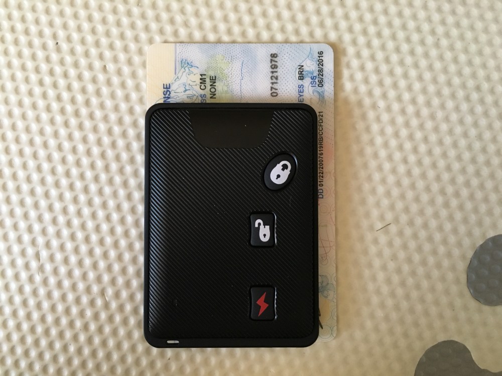
The alarm system I chose to go with is the Digital Guard Dawg iKey system – I hate hate hate the use of “dawg” and i-anything that isn’t actually made by Apple. That aside, this is a pretty neat system. I’ve gotten pretty used to the keyless entry system on my Audi and I was looking for something equivalent in the aftermarket. The DGD system is a PKE – Passive Keyless Entry – alarm system. It will lock and immobilize the car when it detects the key is moved more than ~10 feet from the vehicle. On approach, at about 3-5 feet from the alarm’s sensors, the car unlocks and the system boots up, ready for engine start. All you have to carry is a key that’s slightly larger than a few credit cards.
It’s a really slick system and something the Infinity System should have been. In addition to the immobilizer and passive keyless features, the system also includes relays and fuses for the starter, ignition, and two separate accessory circuits – one switches off during engine cranking and the other stays on. At the time I was looking for a PKE style alarm system this seemed to be the cat’s meow; I’m not sure if anything else has hit the market that’s a close competitor. It’s currently listed at $600 – which I think is CRAZY expensive, but it was selling for about half that during last year’s Black Friday sale which is when I nabbed mine.
I was pretty sure when it came time to start the car there would be issues with integrating the alarm and all that wiring but I was pretty pumped to try and get the engine cranked over once again.
Before I continue – kudos once again to RCR for helping me out by sending me a replacement starter. It really minimized my down-time and was a real pick-me-up after I’d encountered all those issues after the initial engine start.
Before I could power the system back up I needed to re-wire the alternator – recall, the last time I’d started the car it didn’t want to stop because I’d originally wired the alternator to a positive terminal down-stream of my kill-switch. I needed to rectify that so the master disconnect would actually do what it’s supposed to do and kill the power, shutting everything down. To do so I needed to make a new 4-gauge wire for the alternator. On one end I crimped the terminal onto the wire and was in the process of melting some solder (to get a better terminal connection) when it happened.
I got marked by the beast. The squeamish should look away …

Picture this …
- In my left hand I am holding a spool of solder.
- In my right hand I am holding an oxy-acetylene torch.
- In my mouth, I am holding the 4 AWG wire and trying to keep it steady, with one end dipped into the terminal, which is secured by a vise.
I had heated everything up and gotten the solder to flow into the terminal. After shutting off the torch with the fingers of my right hand, I reached over to grab the wire with my left – while still holding the burning hot-tipped solder. Yep. I jabbed myself in the carotid and burned through/cauterized a few layers of flesh before the searing pain jerked my hand away from the wound.
It’s my first real injury working on this car so I suppose I should consider myself lucky it wasn’t any more serious. So now I’ve been permanently branded by the car, aka “the beast”. Don’t ask me why I was doing this, just know that I’m an idiot.
It’s mostly disbelief at my stupidity that hurts, the physical pain isn’t too bad. After taking a moment to shake my head at the new lows of my carelessness it was time to power up the car! (and hopefully not torch the garage).
I had considered recording the power up event in case it all went up in flames, I’d have something to show the insurance company. Really – I really did think that. But in my excitement I decided to forego caution and flip the master disconnect!
Nothing happened …
Huh?
Oh … duh, the PKE alarm system is active and it doesn’t sense the key! I had to root around for a bit to find the key, there are about 1000 boxes in this garage now, some empty, some filled with trash, others with random bolts, and others with critical components yet to be installed – all sitting in a pile. I really need to organize this garage (I’m sure Bob agrees).
With the key in hand, I approached the car and I could hear the relays clicking as I got closer – good progress! The system recognizes the key and started the wake up sequence. As with the Infinity system, the DGD alarm uses a single push button start ignition. Push it once to go to ACC mode, then hold the button down to crank the motor.
Sweet – push the button once. Nothing. Push it again. Nothing. WTH? I grabbed the manual and started tracing wires … everything looked OK. Voltmeter out … voltage looks good, “battery” fuse box is live … what’s going on?
Frustrated, I pushed the button again for sh!ts and giggles. Click. The Aim dash system lit up and started booting. WTH?
Push the button again. Aim system shuts down. OK, so turning it off works…
Push the button again. Nothing. ?!?!?!!!
Then it hit me … push the button again … Aim system boots up, relays are clicking, fuel pumps priming, things are good! A-ha! I was releasing the button too quickly. I needed to pause juuust a bit longer before releasing the button. OK, phew! So everything WAS wired correctly, I guess I was just too excited.
I ran around and checked voltages to various components to make sure all the fuse boxes were powered up and the system was ready for the BIG START. Yep, all’s looking good, time to START THE ENGINE!
Push and hold … Nothing. Huh?
Push and hold, count (one … two … three … four …) Nothing. If it ain’t cranking by now it ain’t cranking, I reluctantly released the button. What the heck now? I had already gone through the wiring to the DGD system and all seemed to be in order there. OK, back to basics – what else do we need to get the engine started?
Ignition signal? Yep, it’s on, GMPP fuse box powered up.
Fuel pumps? Yep, already heard them cycle and verified pressure.
Starter? Oh man … did I get a BUM STARTER?! How bad could my luck really be? Walking to the back of the car, I was feeling a bit gutted and thought I couldn’t possibly have this much bad luck when it comes to starters.
Thankfully, that wasn’t the case. It’s that I’m a moron. Yep, I’d terminated the wire for the starter solenoid but I hadn’t hooked it up yet – it was just dangling next to the starter. Earlier, I had gone around the car and taped off any un-terminated wires to ensure they couldn’t ground out if they energized; while I was doing this I realized I hadn’t terminated and installed my starter wire yet – so I did. But after terminating the wire I realized I hadn’t terminated and installed the ground wire for my lift system up front – so I got up, ran to the front of the car and completed installation of the lift system wiring – and I had forgotten to shove the freshly installed connector onto the starter before going to the front. D’OH!!!
OK … back to the front of the car. Flip the master switch. Click click, DGD recognizes the key, starter button lights up. Push the button … (one one thousand) … let go, fuel pumps priming, other clicks are happening.
Time for the big show, push the button … (one one thousand, two one thousand, three one thousand, four one … ) GAAAH! Why am I cursed?! No love. No engine cranking.
Read through the DGD manual once more.
Oh … “Apply the brake and press-and-hold the start button to START“.
I guess it helps to read the instructions carefully. Once again …
Flip the master switch. GOOD.
Press, pause, release. GOOD.
Press and hold brake pedal. Click. Oooh .. that’s a good sign. And the start button is now flashing!
Pray, press and hold – Grrr Grrr Grrr ROAR … the engine is running and IT IS LOUD! (sorry, I have no idea how to type the sound a starter motor makes as it’s engaging the flywheel, you get the idea).
And that’s it. I let the engine run for a minute or so but it was running so rich my eyes were starting to water and I was having a tough time breathing – yeah, I wasn’t smart enough to turn on the fans, too excited.
Shut the engine down and air out the garage, time to close up shop and go home. Ellie’s about to get home from daycare.
What a way to end the day!
I need to take a bit of a break from the car. I’ve got some projects going on at the house that need my attention and I’ll be spending time with family for the holiday, I suspect it’ll be a bit before the next update.
Soon after getting home our friendly UPS driver dropped this off …

Puzzle solvers rejoice …

