… and I don’t care. Sort of.
In an earlier post I discussed how I planned to bypass the Infinity system from the critical engine operating circuits and how my other design choices reduced the system to something along the lines of a fancy lighting circuit. Welp, I’ve decided I’m going to remove it altogether. There’s no sense tying up that much expensive hardware and only using 30% of its capabilities. I discussed this with Bob and he thought it was a sensible decision. He also volunteered to draw up a new wiring diagram and run all the wiring for me – double score!


I haven’t seen any other SLC build that omits the Infinity system though I suspect they’re out there.
In an even earlier post I discussed how I had literally spent days toiling over where to install the accusump; I even went into a long blathering spiel about how it needed to be mounted upright and how I didn’t want it on the firewall.
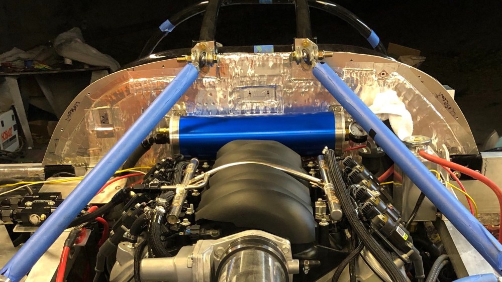
I decided to move it to the firewall.
This morning I walked into the garage and started thinking about how I was going to put all the sound damper/absorber/heat blocker on the upper firewall and as I walked around I couldn’t help but stare at the accumulator. And I hated it.

It looked like a jumbled mess. Granted, some of the wiring and hoses are still temporary until they find their permanent home, but I just didn’t like how I was smashing so many different components into that one little area. It was like the collection point for last minute decisions.
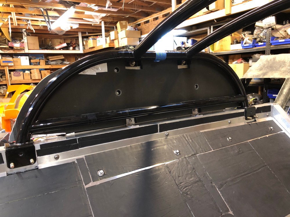
As I considered the upper firewall plate I thought how wonderful a sound board it would make – a large flat surface perfect for engine noise and vibration to really light up. I thought about all the effort I was going through to keep the interior cabin blocked from the engine compartment and how this huge flat surface was just going to transmit everything right into the back of my head. Ultimately this was the little shove I needed to move forward with installing the accusump on the firewall. Now that the Infinity system’s rear power cell was no longer taking up firewall real estate, it left me with a nice wide open area to mount the monstrously large accusump. The accusump would help stiffen the plate (in addition to some additional mounting tabs I had added) and would help to break up the sound waves hitting the firewall.
What about that crazy long OCD laden discussion about dry oil bubbles and seal tearing? I reasoned (hah!) that a semi-regularly driven car would get enough oil sloshing in the cylinder that the chances of developing a dry spot and tearing the interior seal are virtually nil. Using this very same logic I also decided to mount the accusump horizontal in obeisance to my OCD.


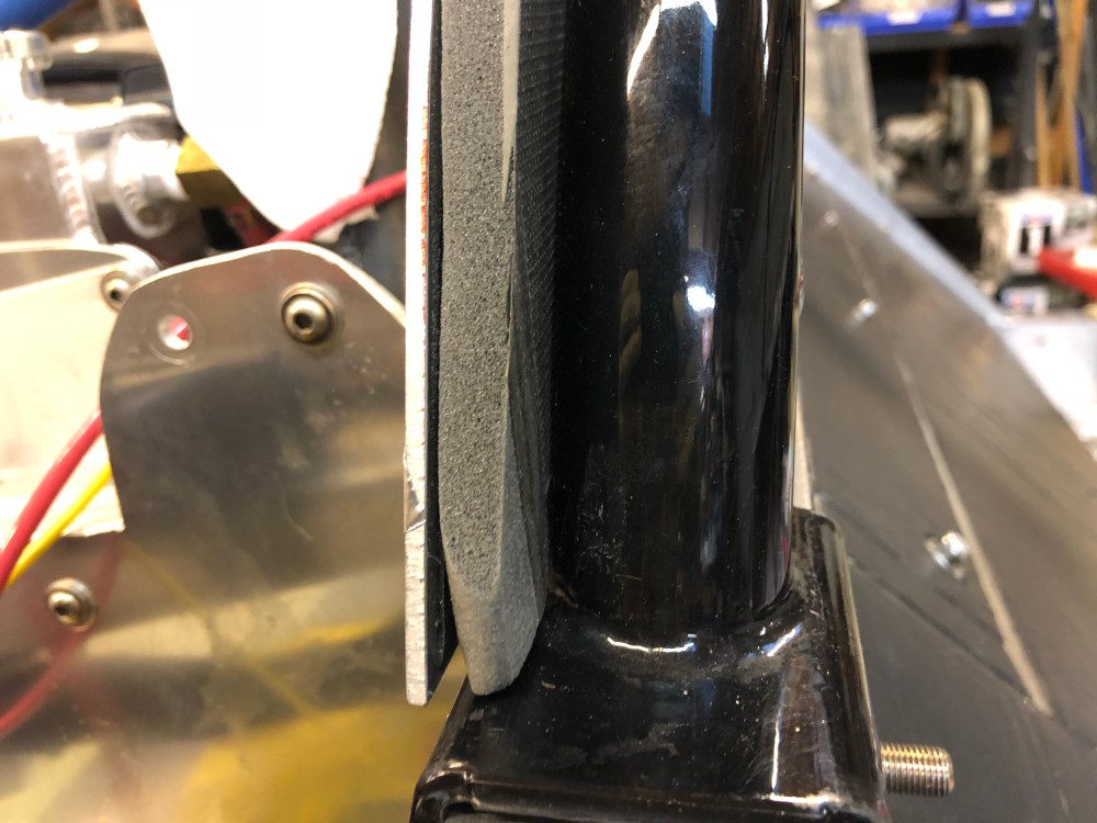
Also in keeping with my flagrant misuse and overconsumption of sound damping material, I installed Damplifier on both sides of the firewall then topped the engine side with a layer of Thermal Block and a layer of Luxury Liner Pro on the passenger side. There’s just enough room between the firewall plate and the roll cage to squeeze in the LLP. I plan to add additional noise and heat blocking material between the LLP and the upper portion of the interior tub.


Alright – that’s a pretty good summary of all the things I’m doing wrong (at least for now). Time to move onto things I’m doing right! In anticipation of getting ready for the first go-karting session I’ve mounted the exhaust test pipes that Bob and Lynn fabricated.


While Lynn was here he also fabbed up a set of rear bellcrank stabilizer plates. The oem design has the pivoting bolt in single shear. This cantilevered design means the bellcrank is less stable; the reality is neither my driving environment nor abilities needs anything more than what has already been designed by the factory.
The engineer in me needs to put the bolt in double shear.
I had conceptually come up with a really simple design for Lynn to fabricate. Once we started mocking things up we discovered the bolt securing the suspension pushrod passes through the axis of the bolt securing the chassis braces. What does this mean? It means the two will crash. So Lynn came up with a design which uses a plate instead of a tube to tie the two points together and he added a few ribs to stiffen the whole thing up. I think Lynn also knocked this one out the park – it may even make me a better driver! (OK, I’m kidding about the better driving part).


You can’t exactly go-kart the car with the throttle pedal sitting on top of the footbox and no functional brakes. It was time to put my big boy pants on and mount my pedals.
I dropped the seat into the frame and used velcro to position the pedals while I turned the steering wheel and made vroom-vroom noises and worked the shifter.

I really struggled to make up my mind on where the pedals should be placed. I originally ordered the adjustable pedal plate but I didn’t like the design of the plate. Lately I’ve been thinking about how I really should build the car “for me” as opposed to building in adjustments for other drivers. I really would like for Bob to drive the car – but at 6’+ it’s difficult to accommodate him and my tiny 5’4″ stature. I decided I would compromise – fixed pedals, adjustable seat.
After moving the pedals back and forth for what seemed like 100 times, I finally settled on a position. I quickly drilled the mounting holes before I could change my mind again. With the holes drilled I turned my attention to acoustic and thermal treatments for the driver’s footbox.


Just a few more (actually, a lot more) items before we can attempt a go-kart session.

One Comment Add yours