*I got a bit lazy and used my cell phone camera to take most of these pics, hence the darkness*
I’ve had the car for about 5 months now and I’ve brought it back to (about) the same state as when I received it! Not exactly the build pace I was hoping for. I recently got a few weeks to work on the car full time and I’ve been having a total blast getting to know the car. Knowing this was only going to be a short period of play before getting back into Phase 2 of the home renovation, I wanted to get my car to a point where I’d be ready to hit it hard once the house is finished.
What I’ve done:
- Stripped down and re-assembled the suspension to a baseline configuration
- (Ahem) polished the suspension – then anodized it
- Powder coated the brake calipers
- Basic suspension alignment
- Basic roll cage, tub, and body alignment
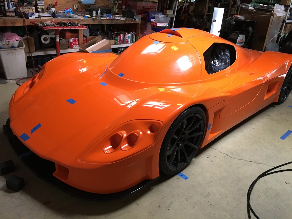
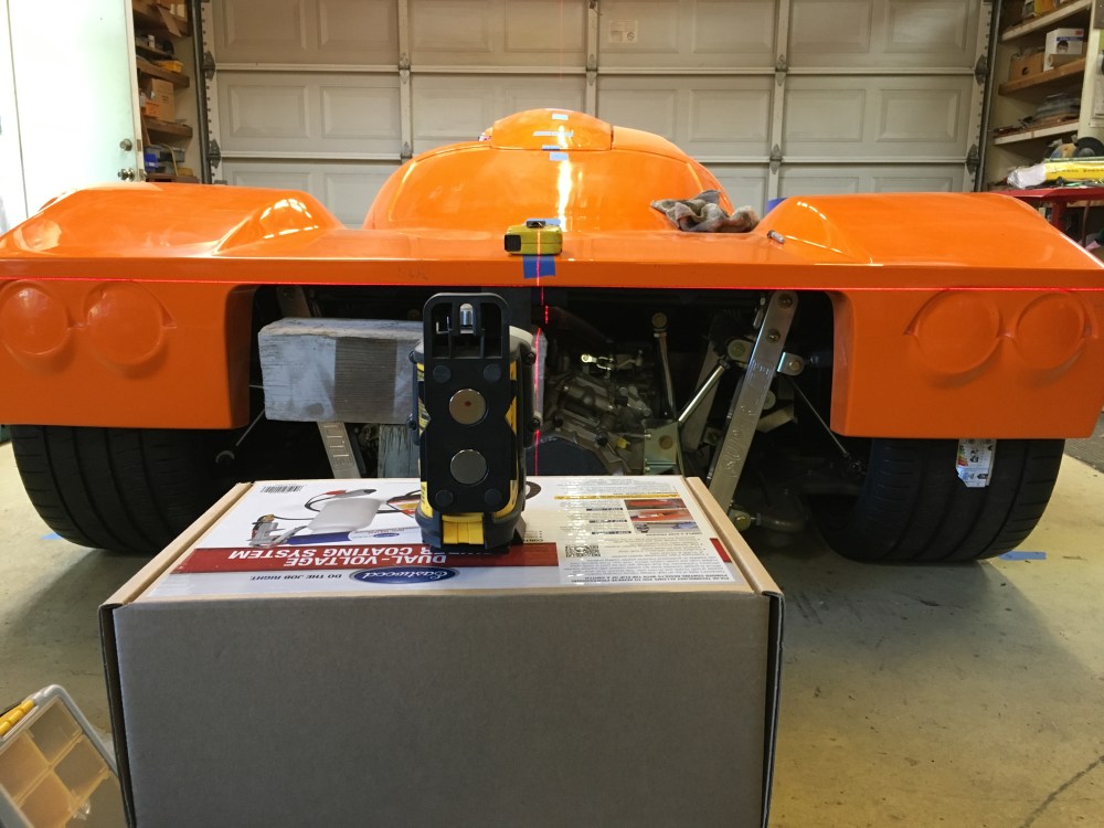
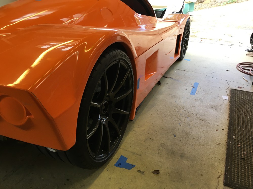
With the suspension hung and body sitting on the chassis, it looks as it did when it arrived from Superlite! However, I’ve learned a lot about how the car was designed, how to adjust the suspension, and I have a better plan of attack for how I’ll be trimming the body panels and aligning/securing the bodywork.
The following is a summary of what I’ve found after performing basic suspension and body alignment. It’s applicable to my car only; your configuration and actual hardware are likely to differ but hopefully this info will help give you a starting point on your build. Having some of this information beforehand would have saved me a few hours! Note I am running the following wheels and tires, YMMV based on your setup:
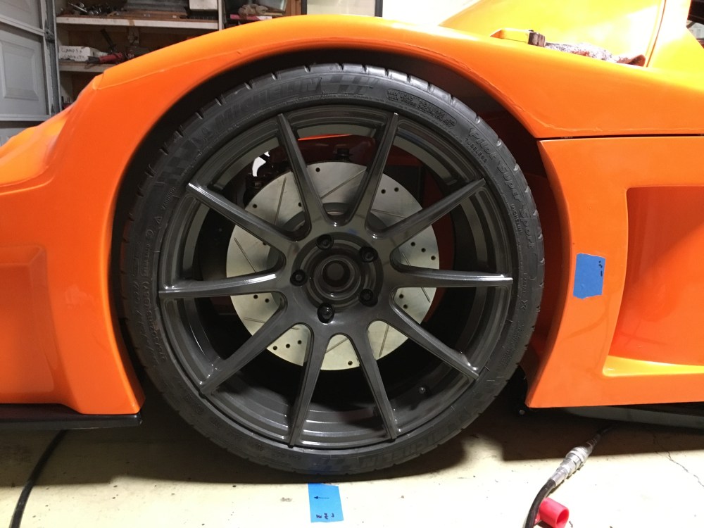
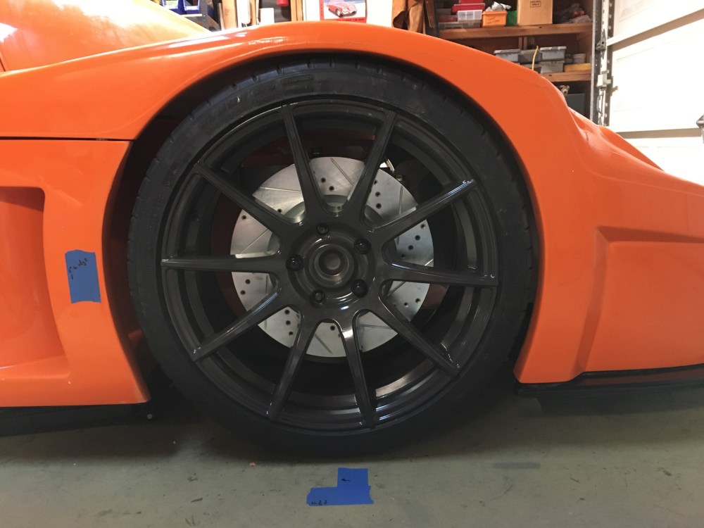
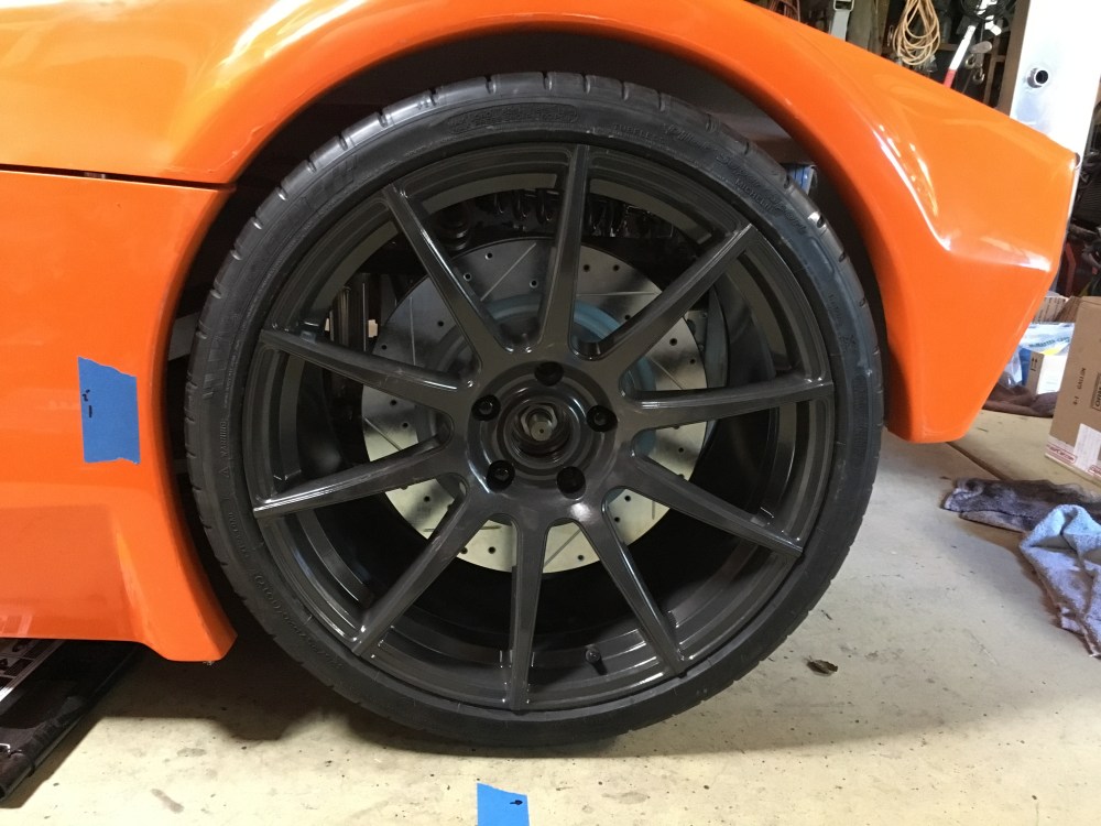
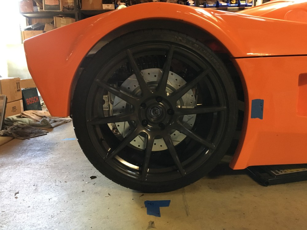
- Forgestar CF10 wheels, 19×10″ front / 20×12″ rear.
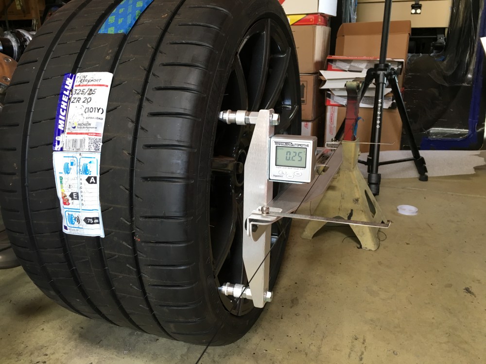
- Michelin Pilot Super Sport (non run-flat) 275/30/19 front, 325/25/20 rear.
- For reference, the factory recommended tire sizing is 285/30/19 front and 325/30/20 or 335/25/20 rear. So my my overall wheel/tire combos for both front and rear are slightly smaller than the factory recommended sizing (may explain some details later). It is recommended to shoot for 26.5″ overall wheel/tire height for the rear with 27″ being the max. Based on feedback from the forum it seems the Nitto Invo 325/30/19 is about the max you want to go and it measures 26.77″.
Alignment plan:
- Install suspension, set rod ends such that ~50-70% of threads are engaged and centered within pickups. – DONE
- Set chassis at intended ride height. – DONE
- Adjust all 4 corners to 0 deg toe and camber (caster is largely built in to the uprights and there’s not much adjustment). – DONE
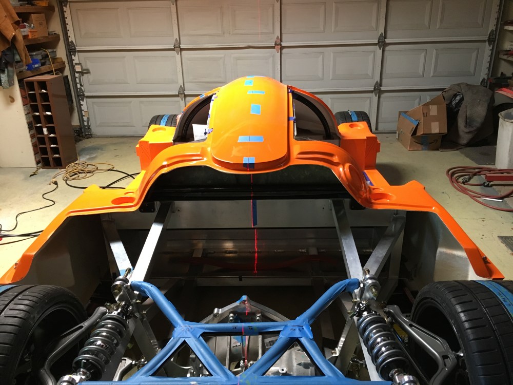
- Hang body, align to vehicle centerline, see how the wheels fit within the wheel wells. – DONE
- Remove body, adjust suspension based on earlier notes. – TO DO
- Reinstall body, verify adjustments were good. Verify sufficient clearance for lock to lock steering at normal and lifted front ride heights. – TO DO
- Remove body and build a car! – TO DO
I wanted to get the suspension somewhat sorted and at a good baseline before jumping too deep into vehicle construction in case something came up with how the suspension or body needed to be adjusted that might undo or complicate some other component install.
Some helpful tips/tools:
- Front LCA rod ends should be adjusted so they are almost max engaged into the control arm. Even with zero threads (past the jam nut) showing on my front LCAs my wheels have about 3/16″ of poke from the fender when set at 0 deg camber. With some camber added I expect this poke will either be eliminated or be reduced such that it’s no longer noticeable/visible. I initially set my front LCAs with about 70% engagement thinking I might need to go one way or the other. After getting my front wheels set to 0 deg camber the UCA rod ends were just way too extended for comfort, so I moved the wheels back in before even hanging the body. After hanging the body it was clear my initial setup would have had way too much poke.
- The two bolts securing the front upper control arms should be shortened so they are just long enough to secure the nut. This allows you to install them such that the nuts are oriented toward the shock body. Why is this important? Because you are now able to adjust front wheel caster/camber/toe without having to remove the shock! With the as-delivered configuration where the bolt heads are oriented toward the shock you’ll need to remove the shock so you can pull each bolt and thereby rotate the inner rod ends. With the shortened bolt mod you can pull the bolts while leaving the shock in place, rotate either the inner or outer rod ends, and secure the upper a-arm back to the chassis. This will require you to support the weight of the chassis while the adjustment is being made (otherwise all that load will go into the shock and the chassis will drop to the floor or bottom your shock, whichever occurs first). If you want to make trackside front suspension adjustments quickly, this mod is a must.
- When adjusting the front upper control arm, one full turn of either the inner or outer rod ends produced a ~0.2-0.25 deg change in camber. This was measured with an initial toe reading of 0 deg, then toe was again adjusted to 0 deg prior to camber delta measurement.
- Make some simple blocks to use as ride height blocks; secure/tape them to the underside of your chassis and remove/wind out the shocks so the springs are carrying little to no load. With the blocks supporting the weight of your car, you can adjust all 4 corners of the suspension without having to lift the vehicle up. This is OK for the initial rough alignment but you’ll want to remove the blocks and put real load on your suspension when doing final verification of your alignment.


- There are a few instances where the factory supplied grade 8 washers were too thick to install when spacing the rod ends within their respective tabs. I ordered a series of washers from McMaster of varying thicknesses so I could eliminate as much slop as possible.
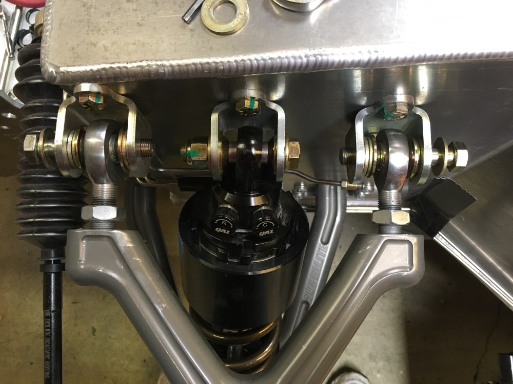
- Be mindful of the bolts being used to attach the various suspension components. The suspension rod ends are secured via bolt and nut. The bolts are spec’d such that the bolt grip length (part that has no threads) should be just slightly wider than the rod end/washer/tab ear stackup. If you find you’ve got a bolt where the threads start between the suspension pickup ears, this bolt needs to be replaced. The “V” portion of the thread is its weakest point and you do not want this located where the bolt will see its highest shear stresses. On my car, I only found 1 instance where a factory-installed bolt had a grip length that was too short. It’s critical that literally every bolt be removed and inspected before being final installed! Bolt on left OK, bolt on right BAD.


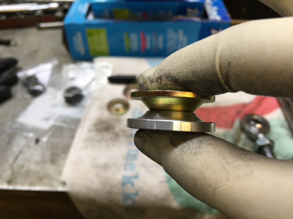
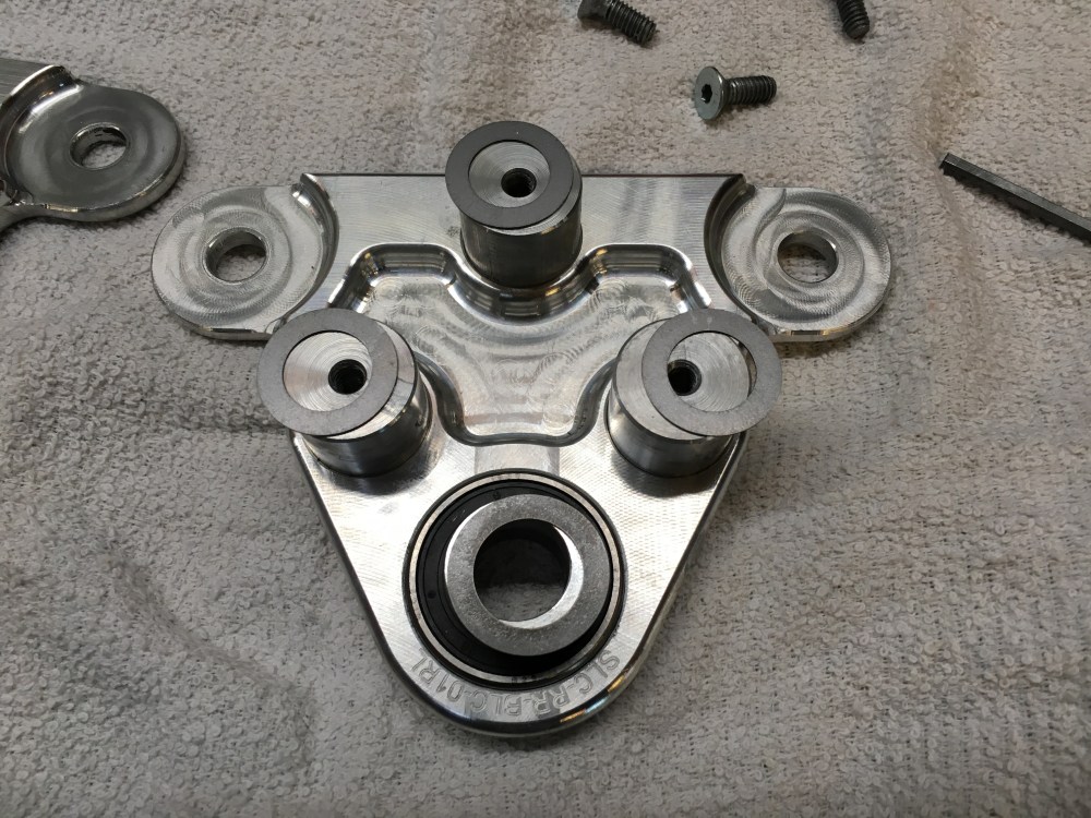
- I had originally planned to eliminate the washer stack below the ball joint/castle nut assembly with a steel machined spacer. I made a steel spacer and combined it with the original castle nut. After further consideration I replaced the spacer/castle nut combination with a standard grade 8 washer and grade 8 locknut. I then followed it up with a cotter pin. This solution seemed to be the cleanest and addresses my concern of potential preload loss at the ball joints.
Left pic is as-delivered and right shows washer/nylon locknut combo.


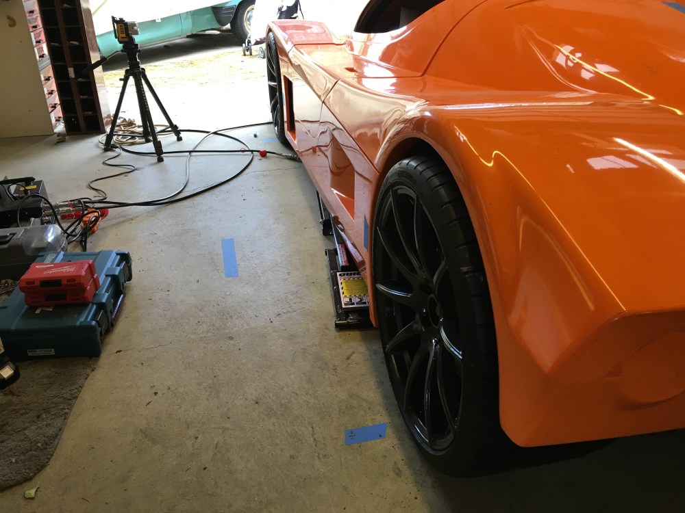
- I’ve been using the Dewalt DW089K 3-beam line laser a LOT. With it, I can draw vertical and horizontal orthogonal lines. When measuring out the chassis or suspension I’ve been using this laser in lieu of jack stands/string. I wish I’d sprung for the next level up laser system (brighter and full 360 beams) but this tool has proven invaluable.
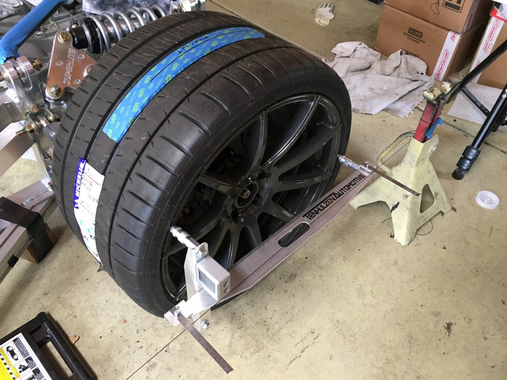
- I’ve been using the Tenhulzen 4-wheel alignment tool (sans string frame) for caster/camber/toe measurements. It’s a really nice and easy to use setup. A bit expensive and maybe overkill for simple DIY, but given how much I’ve used it so far I think it’s been a great investment. There are alternatives that do the same thing but the quality of this piece is really nice – I can’t speak for other units. Having the string frame may make measurements quicker and easier to do; having a single laser makes left-to-right measurements tedious as the laser needs to be moved from side to side. I did try running some strings on jack stands but got tired trying to make the left and right sides match; the string frame looks like it would make this easier. Probably a good investment if you plan to align your car frequently but the tool and laser system worked OK for me.
Observations (YMMV):
- As delivered, a few of my Aluminum safety washers already showed signs of distress from being impacted/jostled during transportation. I decided I wanted to “upgrade” my safety washers to steel at any locations that would see lateral impact loading (placing high stress at the contact face between the washer and rod end). I place “upgrade” in quotes because it creates an additional headache; the steel safety washers are slightly thinner than the supplied Aluminum pieces. This resulted in my having to use different thickness washers to eliminate slop at various locations. It’s a headache I created by swapping to the steel safety washers but I believe this is the more robust solution. I ordered the 3068-08 and 3068-10 washers from Pegasus. There is a side benefit to the steel safety washers in that the profile of the washer will allow greater articulation before the rod end will bottom on the washer.
- Apart from my right rear toe link snafu (also an issue I created myself), the suspension bolted together without issue apart from the rear bellcranks. I measured my rod end to be 0.625″ thick. The supplied washers measured 0.200″ thick (2x needed) for a total stackup of 1.025″. The 3 spacers sandwiched between the bellcrank plates measured 1.000″ thick. To get my push rods installed I either had to force the plates apart or come up with some way to increase the bellcrank spacing. I opted to use 0.025″ shims to push the bellcrank plates further apart; this allowed me to install the push rod heim joint without any resistance. Using shims was an easier solution than re-machining the spacers. Alternatively pushing the plates apart and jamming the rod end in wouldn’t have placed excessive stress on the assembly – my decision to shim was a preference thing. For each bellcrank I used 3x 3088A413 and 1x 3088A414 shims (McMaster PNs).
- Some builders have used the zerk fittings at their balljoints to establish the “center” point of a suspension corner. My front ball joints did not have a threaded hole to accommodate a zerk fitting so I had to come up with a different method. To determine the center point of each suspension corner I set each wheel at 0 deg camber/toe. I then used the laser to shoot a vertical beam which passed through the center of the spindle and across the top of the tire. Prior, I had measured the centerline of the tire tread. Where the center of the tire tread and laser beam cross, I marked this as the “center” of the wheel for track and wheelbase purposes.
- I considered 2 possible ways to align the front to rear wheels; either align them such that the centerline of the wheels were in line or align them such that the outer edges of the wheels were in line. Using the first method the rear wheels would stick out ~1″ further outboard than the front wheels. Using the latter would have the inboard edges of the rear wheels sticking ~2″ closer to vehicle centerline than the inboard edges of the front wheels. After hanging the body I prefer the latter approach for creating a more visually appealing stance. This would technically make front wheel track wider than the rear.
- For reference lines, I used tape placed along various parts of the car and floor. With the laser line system it was easy to use the straight edge of a piece of tape to mark a line. Reference lines transferred to the floor are only good until the vehicle is moved.
- My chassis measured as straight as I could measure using laser and tape measure. Left/right/front/back, everything’s straight, perpendicular, and level. Suspension pick-up points are equal left to right. Given this, I can’t for the life of me figure out where this one discrepancy is coming from; with equal amounts of thread showing on both left and right rear suspension, my right rear wheel sits ~0.5″ further inboard than my left rear wheel. I verified suspension pick up points and rear subframe straightness but did not look at my LCA ball joints or the LCAs themselves. With the amount of adjustment left on both sides, I may have to bring the left side in by the max amount and bring the right side out slightly to have left/right rear track equal.
My numbers after rough alignment/body fitting (note wheels are aligned for 0 deg camber/toe, rod ends centered within pickup tabs with noted exception):
- These measurements have an accuracy of ~1/16″ or slightly better.
- Front and rear ride height currently set at 4″. I’ll be moving ride height to 4.5″ for the next round of setup.
- Current front wheel track is 62-9/16″. Current rear wheel track is 61-3/4″.
- Current left side wheelbase is 104-3/8″. Current right side wheelbase is 104-1/2″.
- Front wheel spindle centerlines aligned fore/aft.
- LF wheel centerline is 31-5/16″ from chassis centerline. LCA inner rod ends have 0 threads showing. UCA inner rod ends have 12 visible threads showing. UCA outer rod end has 6 visible threads showing.
- RF wheel centerline is 31-1/4″ from chassis centerline. LCA inner rod ends have 0 threads showing. UCA inner rod ends have 9 visible threads showing. UCA outer rod end has 8 visible threads showing.
- Left front LCA has 2.15 deg slope; increase ride height to level LCA.
- Right front LCA has 1.9 deg slope; increase ride height to level LCA.
- Rear wheel spindle centerlines are misaligned; the RR wheel sits ~1/4″ further back than the LR wheel. The RR forward UCA rod end is not currently centered within the suspension tabs.
- LR wheel centerline is 31-1/8″ from chassis centerline. LCA inner rod ends have 5 visible threads. UCA inner rod ends have 5 visible threads, outer rod end has 5 visible threads.
- RR wheel centerline is 30-5/8″ from chassis centerline. LCA inner rod ends have 6 visible threads. UCA inner rod ends have 6 visible threads, outer rod end has 5 visible threads.
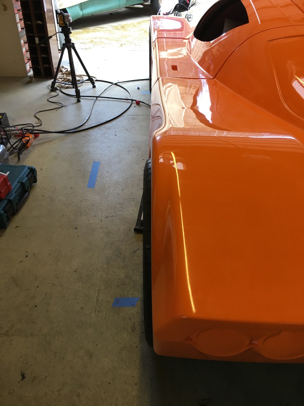
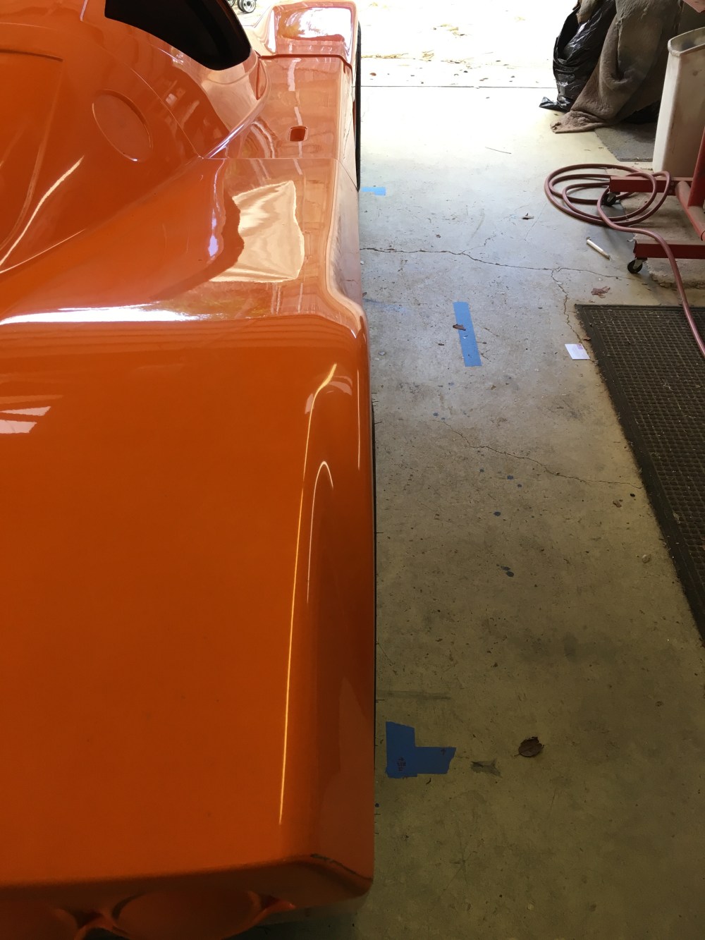
Wheel well clearance numbers are measured from the edge of the wheel well to the edge of the RIM, not tire OD.
- LF wheel to wheel well clearances: 3-1/16″ (top) / 3″ (front) / 3-3/4″ (back).
- RF wheel to wheel well clearances: 2-3/4″ (top) / 3″ (front) / 3-5/8″ (back); RF corner of front clip was visibly misaligned, couldn’t get it to sit on the alignment pins quite right.
- LR wheel to wheel well clearances: 3-7/8″ (top) / 3″ (front) / 3-3/8″ (back).
- RR wheel to wheel well clearances: 3-1/2″ (top) / 3-3/8″ (front) / 2-3/4″ (back).
Given the above measurements, I’ll need to do the following next:
- Raise ride height; ~4.5″ sets the front LCAs at horizontal.
- Push RF wheel outboard 1/16″.
- Push both front wheels rearward ~3/8″.
- Adjust rear wheels for fore/aft spindle alignment; RR wheel moves forward 1/4″. Some shaving of the wheel wells needed to evenly distribute gap.
- Adjust rear wheels for equal track: push LR inboard max, push RR outboard as necessary to match LR.
She’s all put back together for now; settling in for another break as we get back into the home renovation gig.