Wing angle:
I couldn’t find any information on wing mounting angle so here’s some information for those who purchased the carbon wing option. The carbon wing is made using the Selig 1223 airfoil geometry. There’s an cool site which has a good bit of technical data on this wing profile here.
Here’s some data for the Selig 1223 airfoil from that site:

In the charts above, Alpha is wing angle of attack (AoA). The various colors represent Reynolds number. If you want to read up on Reynolds number, hit up Wikipedia. For the sake of this blog post you can think of Reynolds number as speed. As vehicle speed (or airspeed) increases, Reynolds number increases. If you’ve read the Wikipedia entry you’ll see that Reynolds number can be analogous to vehicle speed because in our case the characteristic length is the rear wing chord length (which is fixed) and the kinematic viscosity of air (for our purposes) remains fixed.
I’m not an aerospace engineer and it’s been a very long time since I’ve had to think about this stuff so here’s my layman’s attempt at explaining the graphs. In our case, a positive alpha angle means the nose of the wing is lower relative to the rear. Angle is referenced to the wing’s chord line, NOT by the angle achieved by placing a straight edge across the wing.
- The Cl vs Cd graph says this airfoil is great at producing lift (or in our case downforce) with very little drag.
- The Cl vs Alpha graph tells us how much downforce the wing produces at various angles. You don’t want to run an angle less than -2deg (nose up) or more than +13deg (nose down). Outside of these angles and the wing breaks down, either producing basically zero downforce or stalling out and not producing any additional downforce – just more drag!
- The Cl/Cd vs Alpha graph tells us what angles will provide us with a balance of downforce versus drag. Peak downforce/drag occurs at about +5deg. Running a more aggressive AoA will continue producing more lift, but the rate at which drag is being produced increases quicker past +5deg.
- The Cd vs Alpha graph tells us the rate at which drag increases stays relatively flat up to about +5 deg. For the Reynolds numbers that matter, it’s relatively linear until you get to about +12deg at which point drag really starts to take off (at least based on the info available).
So what does all this mean for the SLC builder? The following table shows rear wing AoA for my car. Note that these measurements include a 1″ vehicle rake (my ride height is 4.5″F/5.5″R). These measurements also include any production and assembly variation unique to my car. I don’t think it’s going to be all that much different for other builders but keep in mind my numbers may be +/- 1deg relative to your car. To compensate for different vehicle rakes, adjust my measurements by ~0.55deg for every 1″ change in vehicle rake. For instance setting 1 on my car as it sits measures +9.75deg. If I were to shift my vehicle rake so front and rear ride heights were equal (-1″ height change in rear) then my expected wing angle would be +9.75 – 0.55 = 9.2deg.
The vehicle rake/AoA relationship tells me that vehicle rake isn’t really sensitive to dynamic ride height changes. The difference between static to dynamic wing angle is probably on the order of +/- 0.75deg – and I’m thinking that’s likely too generous.
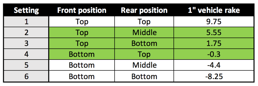
- Configuring your wing for setting 4 is pretty safe. Just about any build or suspension setting you may have puts the wing right at about 0 deg. At this setting the coefficient of drag is relatively flat. This is the lowest AoA you want to run.
- Setting 3 gets you more downforce while still being in the flatter range for drag. You get about a 20% increase in downforce (relative to setting 4) with a minor increase in drag. Probably OK for any street configuration car that’s keeping reasonable speeds.
- Setting 2 is the most optimized setting for downforce vs drag. You’ll get about a 55% increase in downforce (relative to setting 4). This is probably the most aggressive setting you’ll want to use. It seems the SLC has a greater issue with not enough front end downforce relative to rear and this setting is likely too aggressive for the standard street splitter. Those running track or race splitters may be able to run this setting. Probably the maximum setting most people will ever use.
- Setting 1 is the big dog position. You’ll get about twice as much downforce in this position relative to setting 4. There’s likely no risk of the wing’s performance completely falling out – this is an assumption I’m making as the graphs top out at a speed of ~70mph. However, at low speeds this AoA makes the wing act like an air brake and if you didn’t have front grip issues with setting 2 you’re very likely to have issues with this position. Probably only appropriate for an all-out race car with serious aero considerations/modifications.
I plan to configure the car to setting 4 to begin with and once I get comfortable with the car’s handling I plan to step it up to setting 3. If anyone reading has advice otherwise, please let me know!
For those wanting to measure your own wing angle, the chord angle (or AoA) is approximately +2.65deg relative to the measurement you’d get if you laid a straight edge across the wing – note, this is only valid if you have the carbon wing option!
Rear wing endplates:
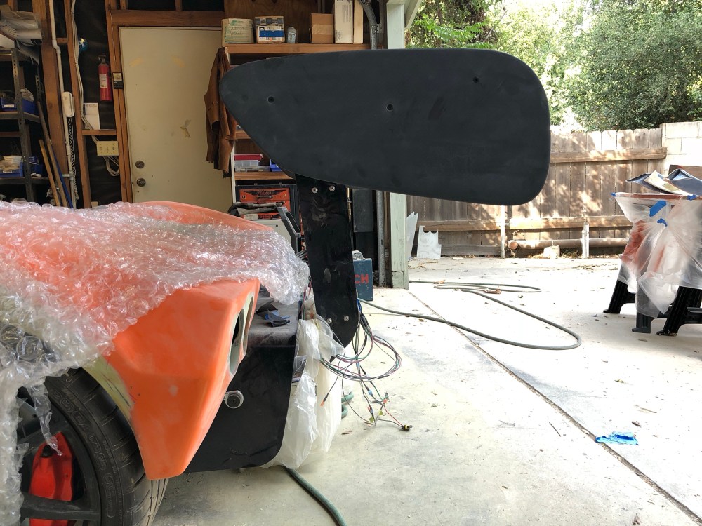
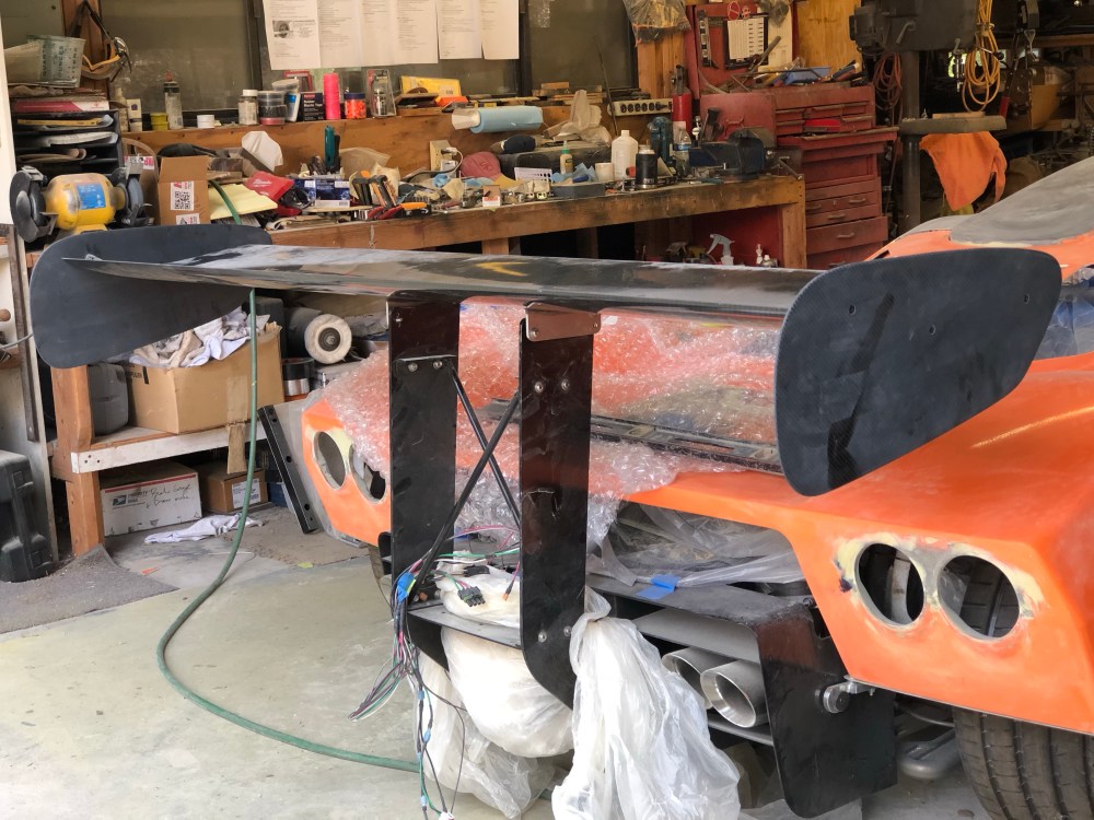
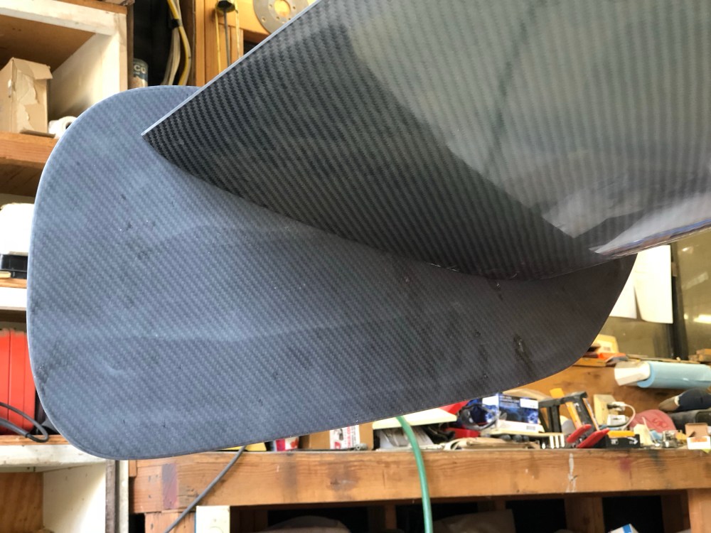
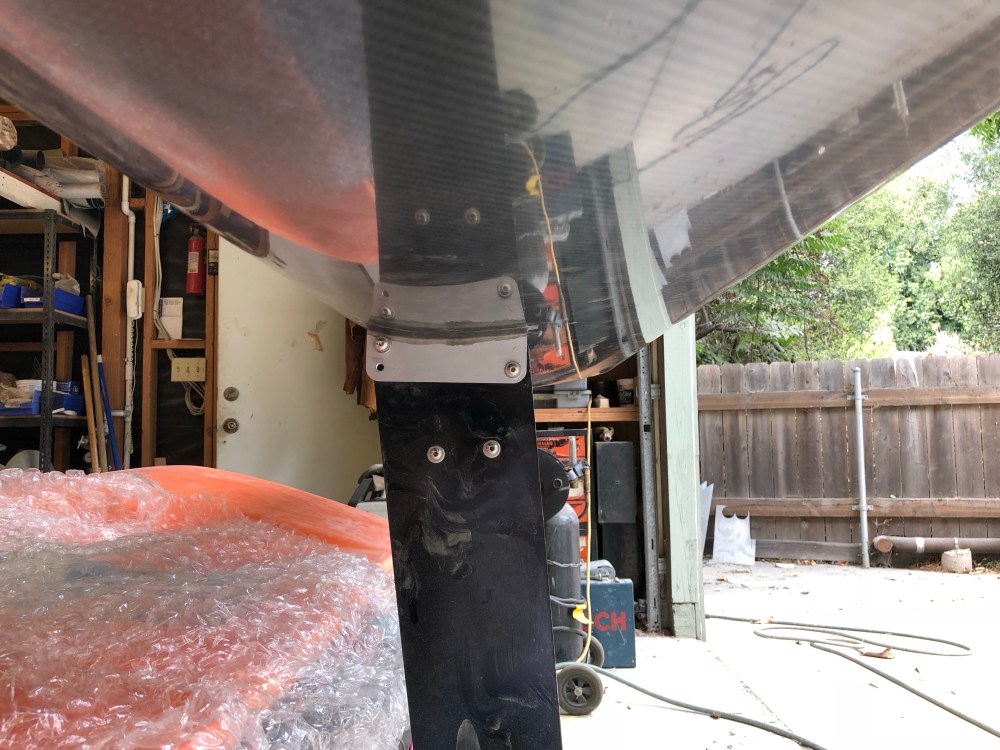
I was concerned about using the RCR supplied endplates; they’re made from 1/8″ aluminum and the wing is positioned at a great height for someone to walk into and cut themselves pretty badly if they’re not paying attention. I also wanted to use the “old school” smaller profile endplates that the earlier cars came with. It may not be as aero efficient but I didn’t want the car to go too far into the “race” looks. Thanks to HJones for hooking me up with a template of the older design.
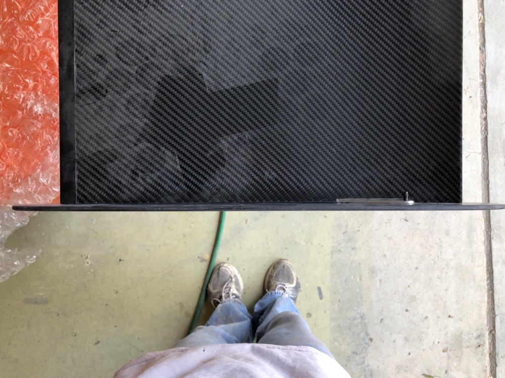
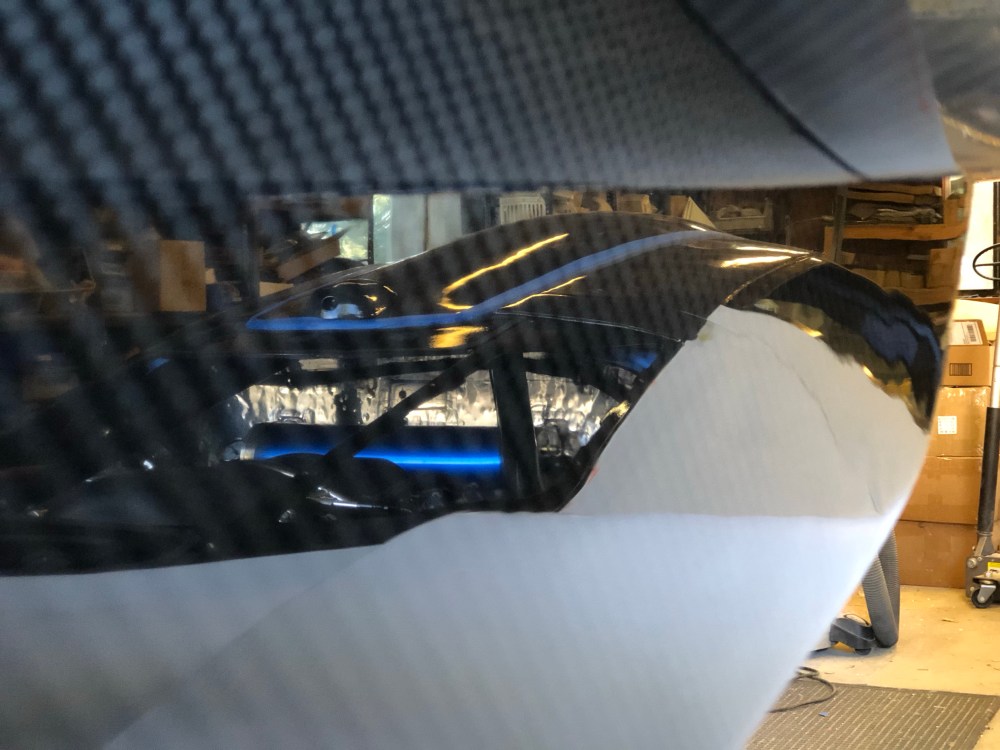
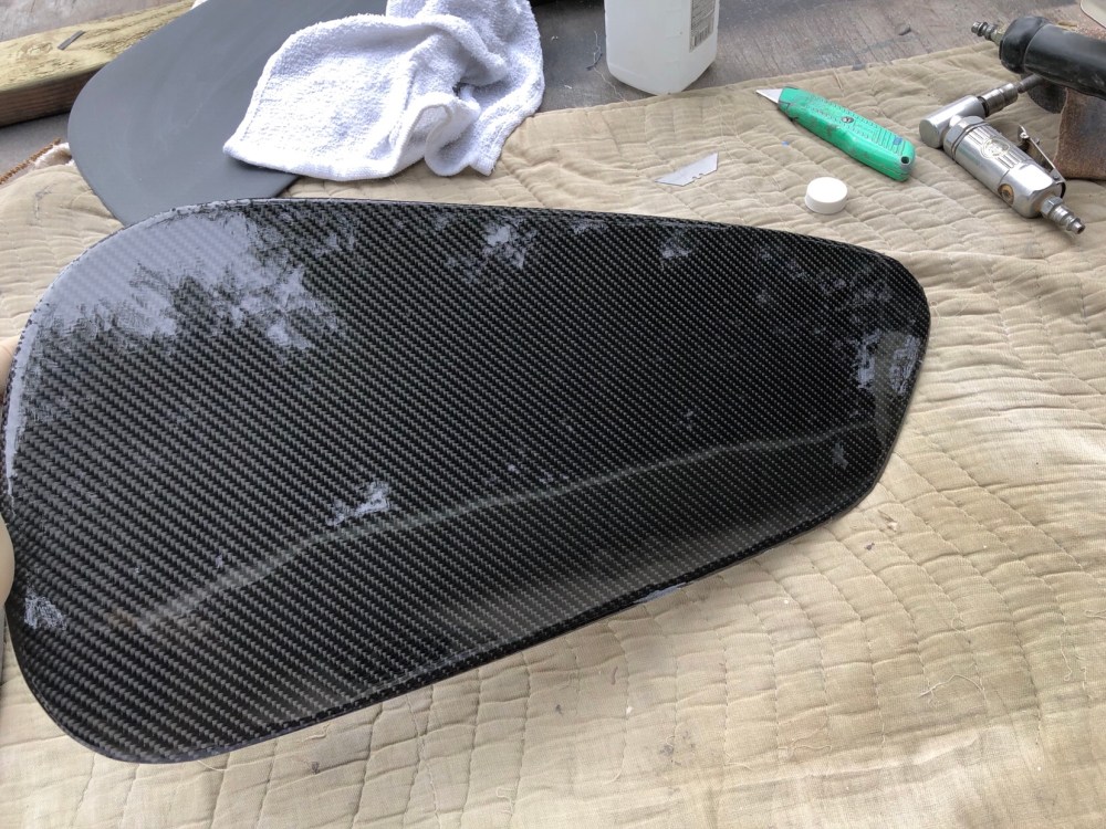
These are fiberglass core plates with both sides covered in carbon fiber. They’re even stiffer than if I’d made them from the aluminum sheet. I was really jazzed with how well these turned out!


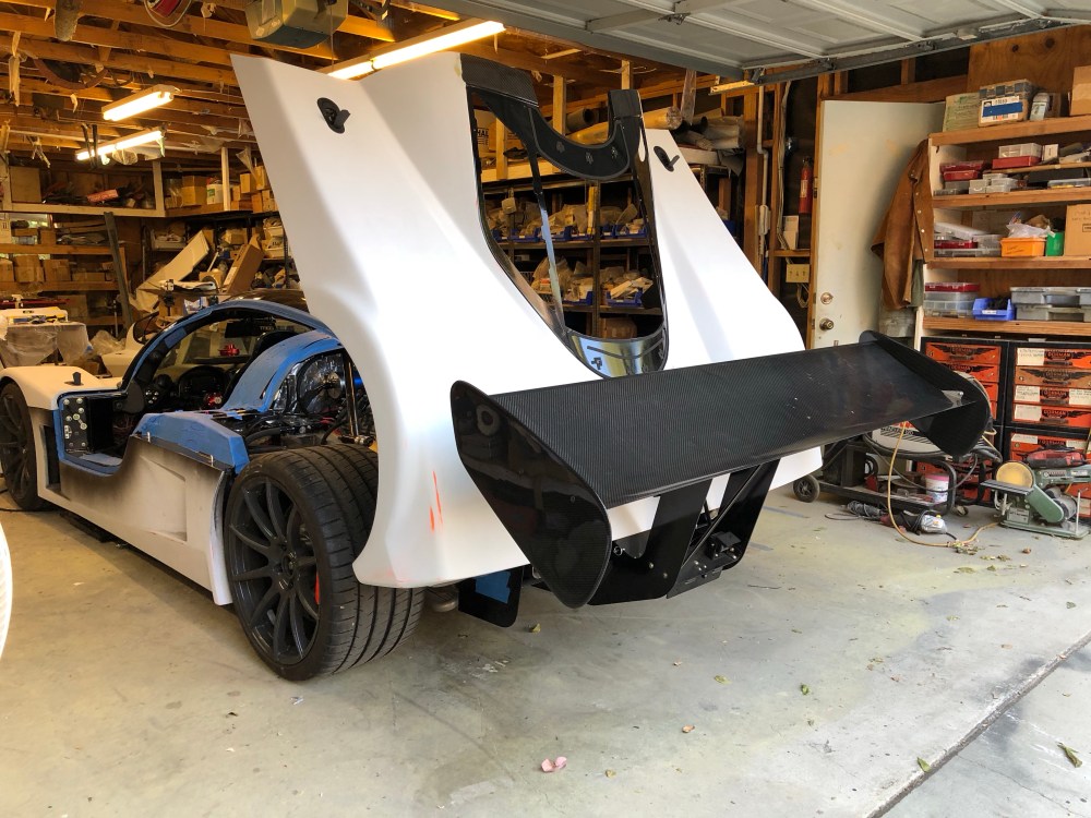
I needed to drill the endplate mounting holes but wanted to get the wing on the car so I could position the plate. Since I knew I was likely to run either setting 3 or 4, I tried to set the plates so they would be relatively level in these positions.