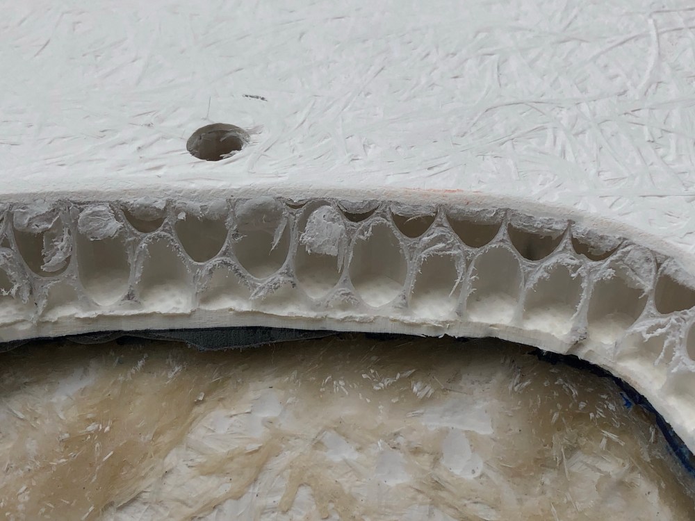
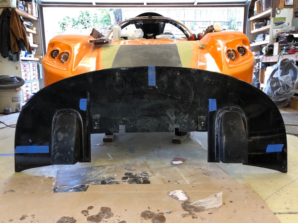
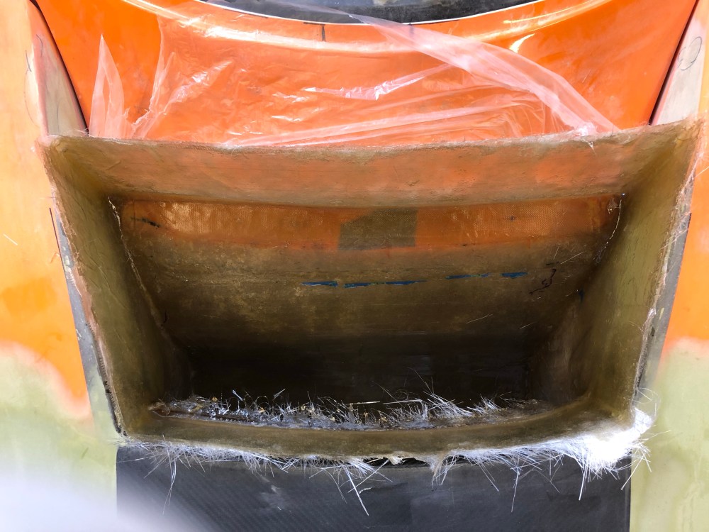
When I spec’d out my kit I had a really difficult time deciding between the street splitter versus the track splitter. Ironically, the higher performance track splitter is actually cheaper than the street splitter. This had me scratching my head for a bit but I eventually discovered the track splitter comes as a “skin” whereas the street splitter is ready to use as-received (kind of). The track splitter “skin” is a thin shell of the splitter, it’s up to the builder to make the “guts” of the splitter so it’s solid. The street splitter is made up of a fiberglass honeycomb core sandwiched between sheets of fiberglass. It’s solid and can be installed and used without further modification – that is, unless you’re as worried about front end aerodynamics as I am.
The real reason I didn’t go with the track splitter is it lowers front end ground clearance by 1-2″. For my street car, and on the steep grades around my neighborhood, that ground clearance is critical. At the time of ordering I wasn’t aware the track splitter needed so much modification to make useful – I’d have been a bit frustrated getting the part and realizing this after the fact. So here’s your warning future builders!
Of course the path I went down required a fair bit of modification of the street splitter anyway.
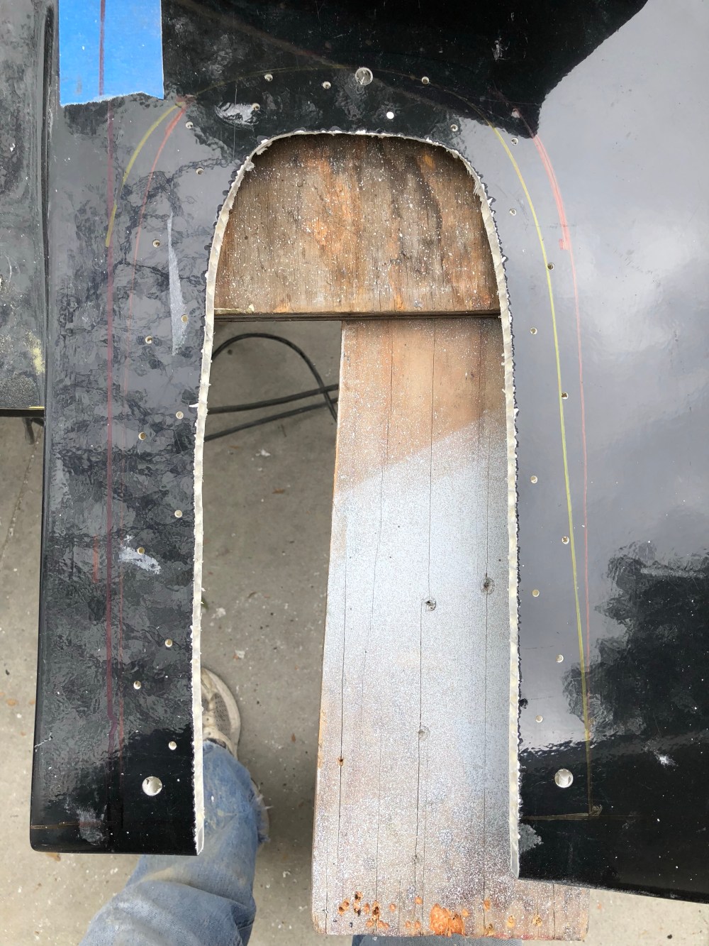
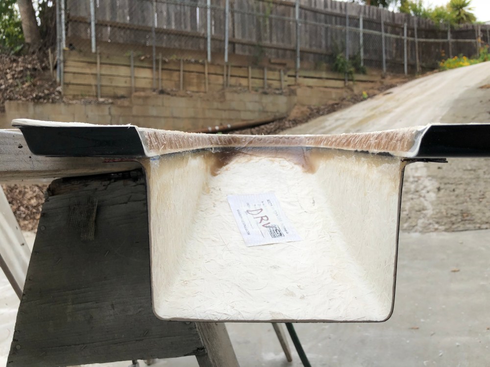
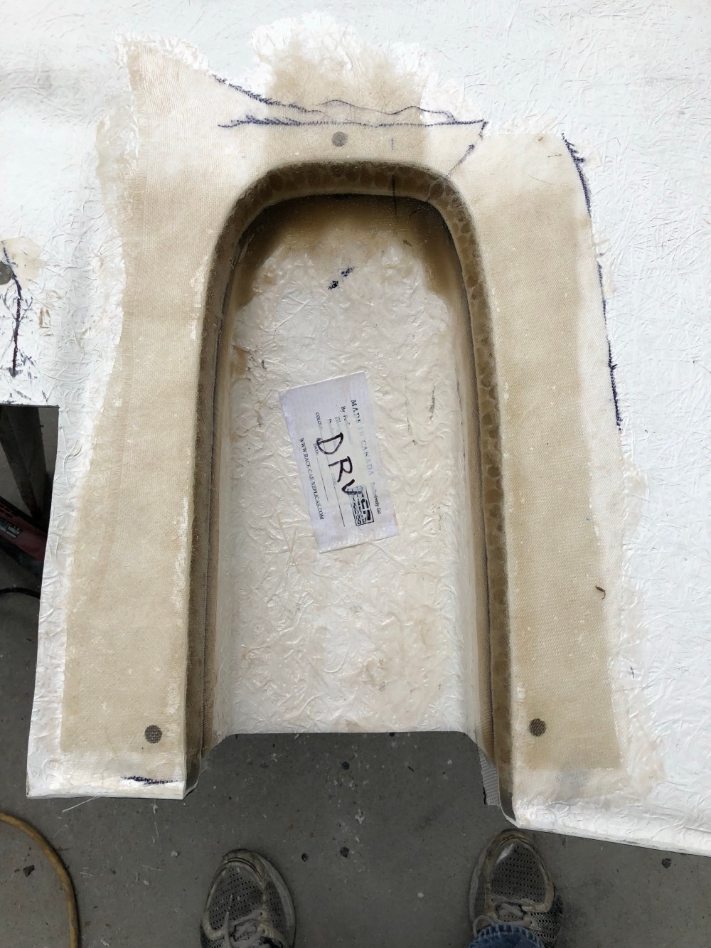
I added the splitter tunnels for my street splitter. The tunnels are large expansion chambers you add to the splitter to create a venturi effect under the nose of the car. This in turn creates additional downforce. On a car with a big wing on the back end, more front end downforce is critical for maintaining aero balance of the car.
Here’s what I did to install the splitter tunnels:


If there are any motorsport/aero engineers out there reading this I’d be interested in getting a lesson!
I hemmed and hawed for a very long time about whether I wanted to install a hinge for my front clam. A hinge would make it MUCH easier to service the front end of the car (hydraulic, brake, clutch fluid reservoirs, lift pump, brake residual valves). It would also add more complexity – not only just designing/packaging a hinge, but also to the layout of everything inside the front clam.
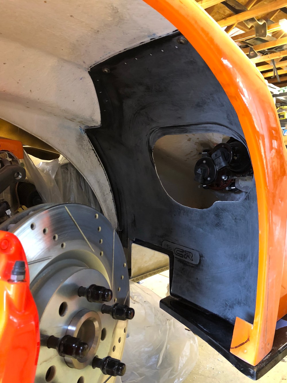
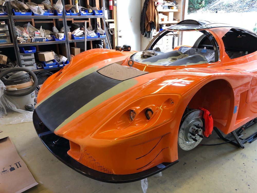
One of the complicating issues is with the front wheel well liner. The liner closely hugs the front tire and sits squarely in the way of where you want to install the outboard splitter support rod. Generally this rod attaches near the rear of the radiator box and extends to the front or rear corner of the splitter. If running the front wheel liner, the arc it swings as the clam hinges forward cuts right through the middle of the liner – the liner would have to lose about 50% surface area down the middle for the support rod to exist. If, on the other hand, the support rod attachment point were pushed forward, to the middle of the radiator box, the lower 50% of the liner would have to be removed – also not acceptable.
I prioritized keeping the liner intact and figured I would very rarely be servicing the components up front – so I finally decided to make the front clam fixed. Once I made this decision, laying out the splitter and front end hardware became much easier/clearer. As is typical, the rear area of the front clam will be secured to the spider via aerocatch latches. At the front, I’ll be using 2 quick-release spring loaded pins.
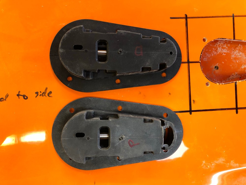
Aerocatch latches:
The “nose latch” is typically located just inboard of the upper surface for the front wheel vent. This location keeps the latch hidden and is the normal location most builders choose to use. I opted to go down a less traveled path (no surprise!).
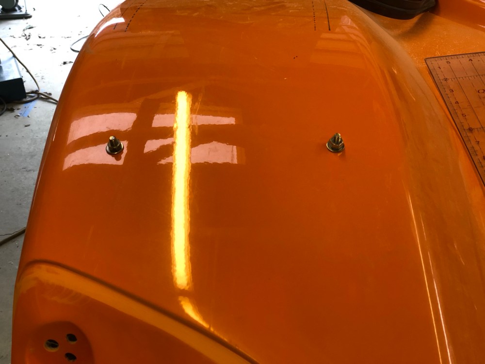
My issue with the typical location is the clamping force is applied along the exterior of the body only. If your bodywork is perfect (or you spent a lot of time shaping the front) this is fine. However, I had a few issues with my body that necessitated a different solution.
With the front resting on the splitter the rear edges of my front clam wouldn’t seat and align with my spider. Using pressure along the exterior edge only, I could get the body to close and seat against the alignment pins – cool. But the issue is the interior edge which meets the spider/windshield area remains proud and there’s a visible step down toward the spider.


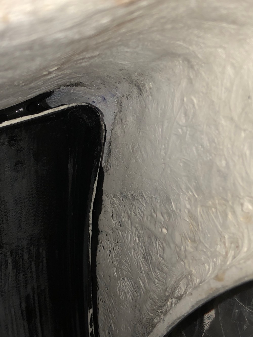
I had a more severe misalignment issue on the passenger side. At first I thought this was due to me hacking the interior so I could create the larger radiator exit – but going back to my as-received photos it looks like this condition existed back then.

**Miracle of miracles, after I bonded the forward parts of my wheel liners it seems I must have locked the front end in such a way that this “tipping” of the front end has rectified itself! I still have the fit issue between the interior and exterior, but the outermost gap is now just about dead on.**
If you haven’t figured it out by now, I opted to position my nose latches along the top instead of hidden in the wheel vents. Placing the latch on the top allows me to center the load – improving the load distribution and helping with my interior/exterior gap issue. It’s not as nice aesthetically but I’m a poseur and can claim “race car” looks ;).
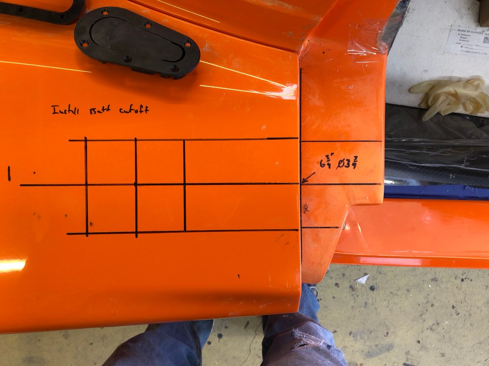
Positioning the aerocatch took me some thinking – and I may have out-sussed myself. Initially I wanted to position the latch body centered over the front “beer can holder”. It’s a ~3.75″ round depression in the front spider – a vestige of an older latch design. The latch body is too big to fully sit within the cup but with enough of a vertical gap, it may be possible. Instead of going the easier route I had to go with the more difficult. Instead, I opted to center the latch pin within the round depression. This pushes the latch body aft just slightly – enough that it now interferes with the spider :(. In hindsight I think I should have tried centering the latch body with the center of the depression, pushing the latch pin forward just slightly. (sigh) 20/20.
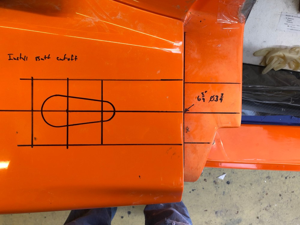

Once I get the bodywork off again I’ll install the latch pin. My plan is to reinforce the cup holder by bonding a sheet of aluminum onto the underside. I then plan to bond a nut to that plate so I can make pin height adjustments without having to reach the lower nut. An upper nut will be placed on the top side – tightening the upper nut will act as a jam nut, securing the pin in place. If the lower nut isn’t fixed some method of accessing it would be required to make pin height adjustments – a very difficult place to reach unless you cut an access “window” somewhere else in the body.
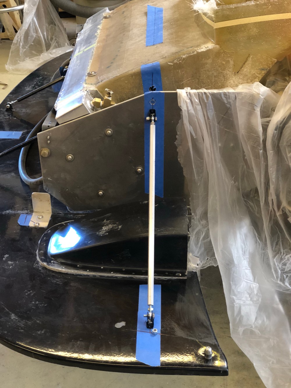
The forward securing mechanism becomes much easier and cleaner without the hinge requirement. I bonded and bolted an aluminum plate to the internal vertical fiberglass fins (belt & suspenders!). On the splitter, I bolted a piece of L-metal that butts against my reinforcement. I’ll then drill a hole through both pieces of metal and secure them with a quick release pin. To remove the front clam I would pull the 2 release pins and undo the aerocatches. I would then need a strong buddy to help me lift the front off the car. It’s not as elegant as a hinged front but I think this is the best solution for me.

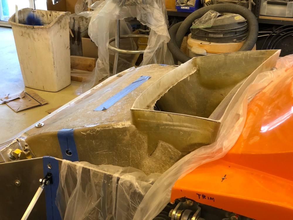
Because I recontoured the front edge of my front wheel wells, the factory-located splitter could be pushed forward another ~0.5″ inch. The new position gives me just enough clearance I shouldn’t have any tire rubs with the suspension at full droop, or while turning the wheel with my front lift engaged. I think it’s critical the wheels can be turned lock to lock while the lift is engaged as it’s a necessary maneuver when approaching sharp elevation transitions in the road.

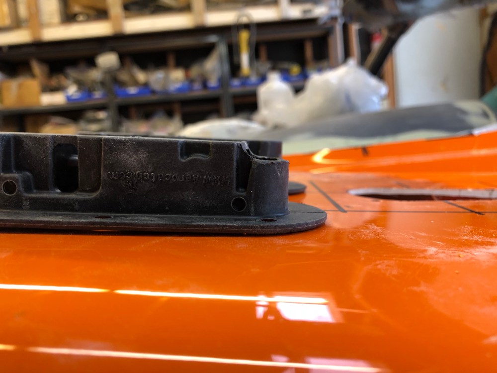
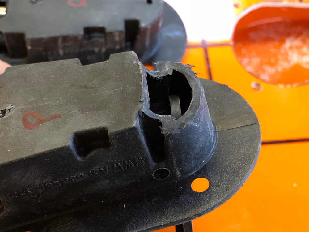
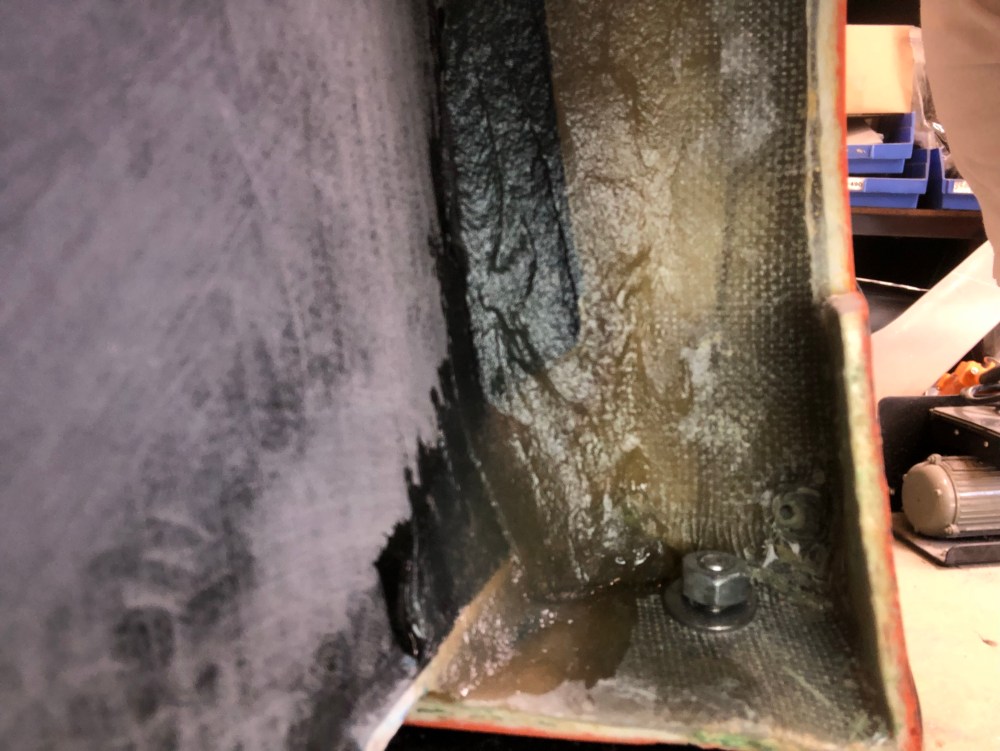
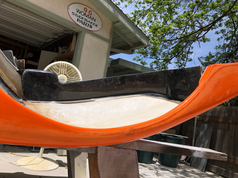
With the splitter’s fore/aft location defined I could now locate the rear splitter support strut. I debated pushing the strut’s anchor point on the splitter forward but decided to keep it perpendicular to the radiator box, keeping it as far back as possible without interfering with the front wheel well liner. Using my hand, I supported the splitter near the front corner then at the rear. With support at the front, I could get the splitter to make a pretty good knocking sound by lightly tapping it – the rear corner was separating from the body and making a knocking sound as it came back. With some rubber/felt here it would lessen the sound but I didn’t want the back end of the splitter wagging around, cantilevered in the air.

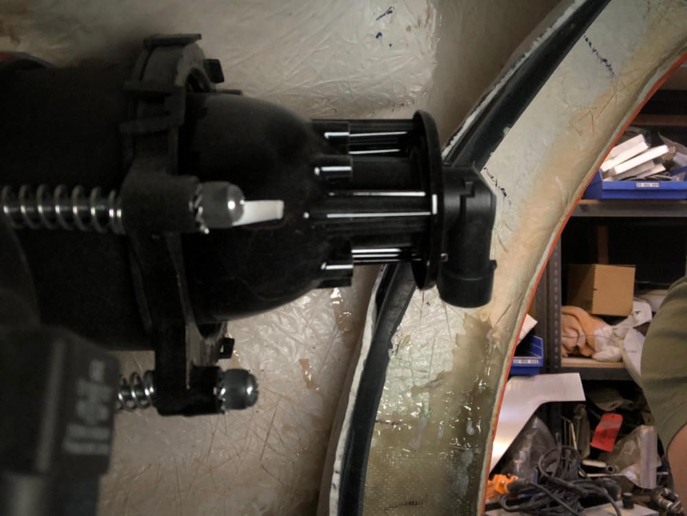
If using the factory-supplied strut parts you’ll want to have 1/4-20 left & right hand taps handy as the provided rods are cut-to-length and not pre-tapped. I used a standard through-hole tap from McMaster and tapped it as deep as it would go. It turned out I needed to shorten the supplied eye bolts by about 1″ to achieve the proper amount of thread engagement and adjustability.

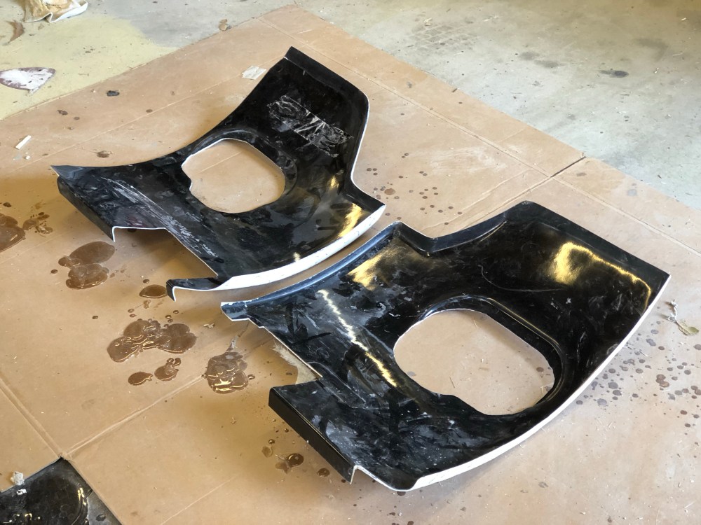
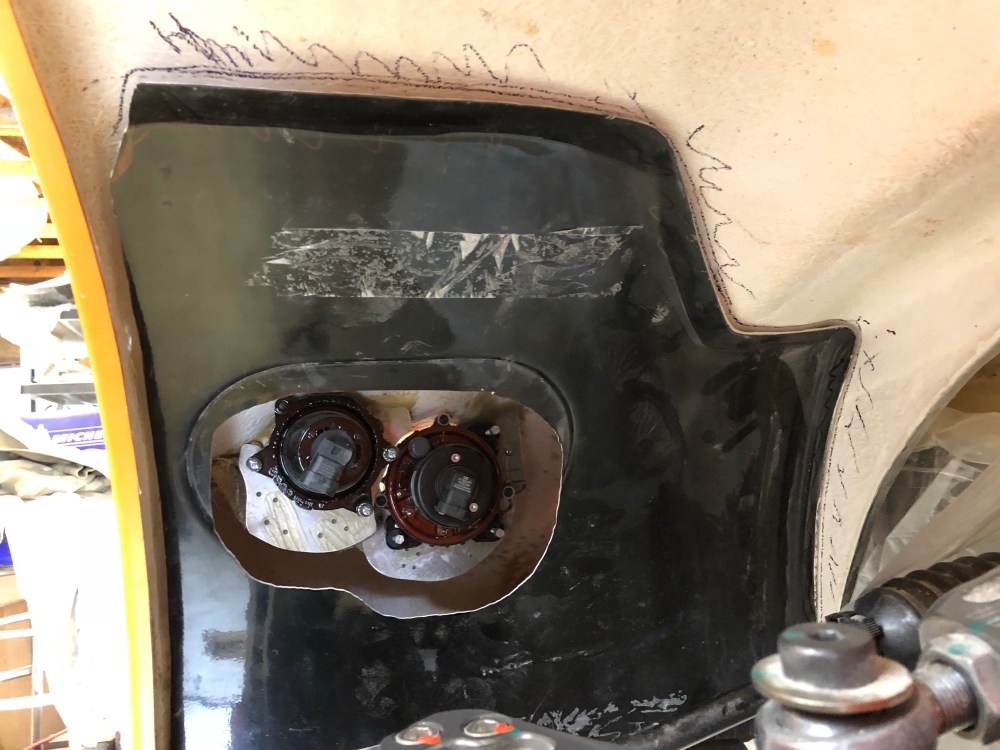
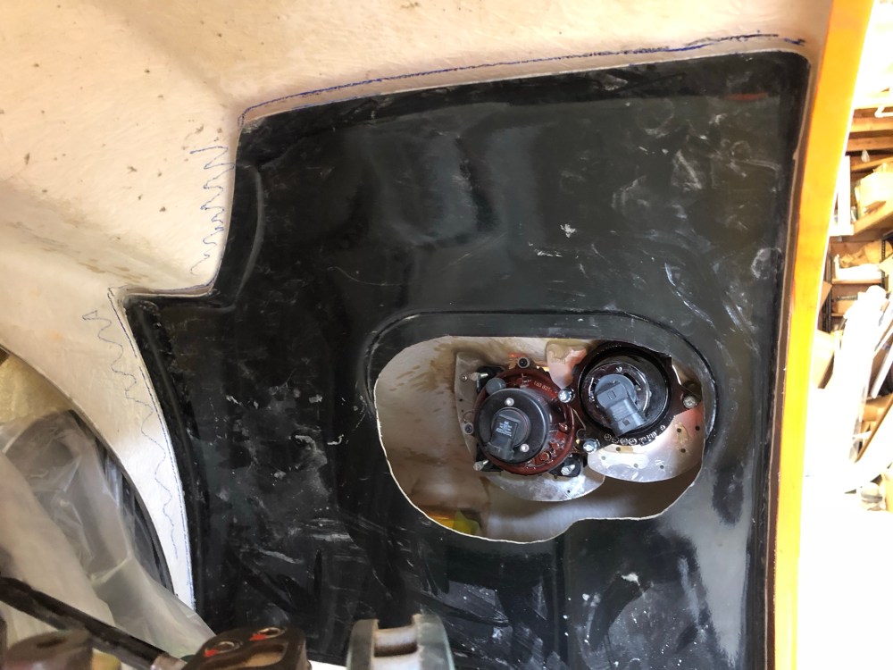
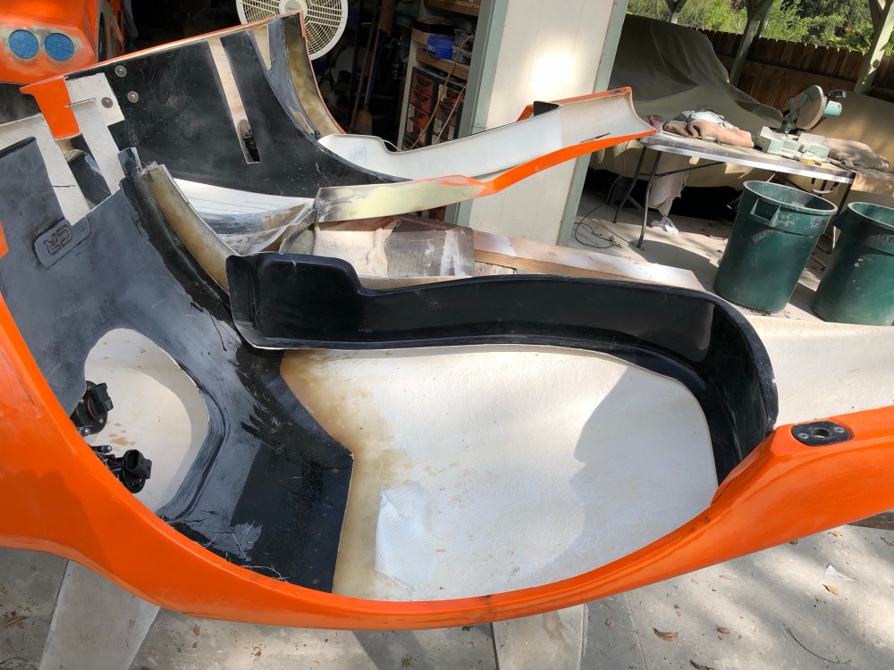
An outline of the wheel well liner can be seen on the interior vertical fin. I was able to rough fit the liners after a good amount of massaging. I covered some of that in post 27. My passenger side liner fit pretty well but the driver side needed a good bit of trimming. I also had to cut holes for the tunnels and access for the headlights and turn signals. I originally cut the holes large enough so I could get proper line of sight to my headlight adjustment screws. Turns out I’ll need to make them even larger so I can get line of sight to the turn signals as well (there’s very little room between the turn signal and liner once installed) – I’ll save that for after the liners are bonded into place.
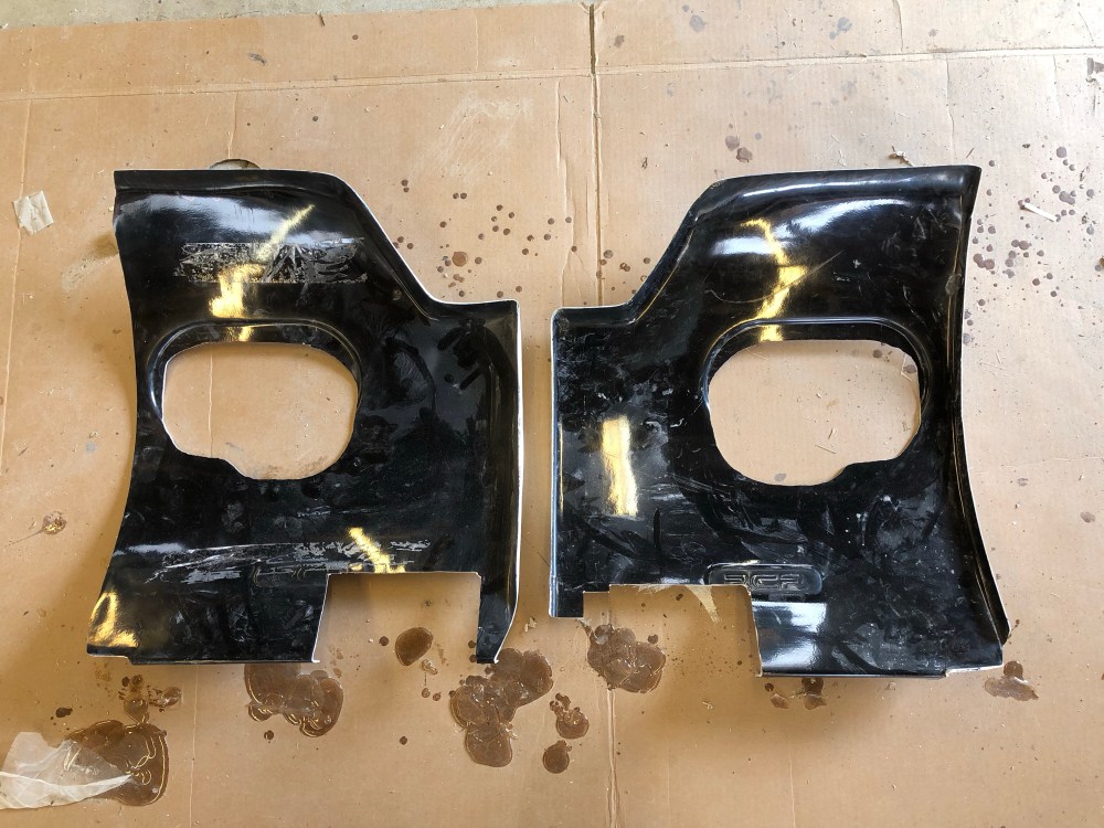
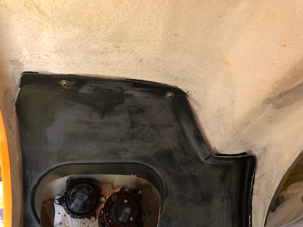

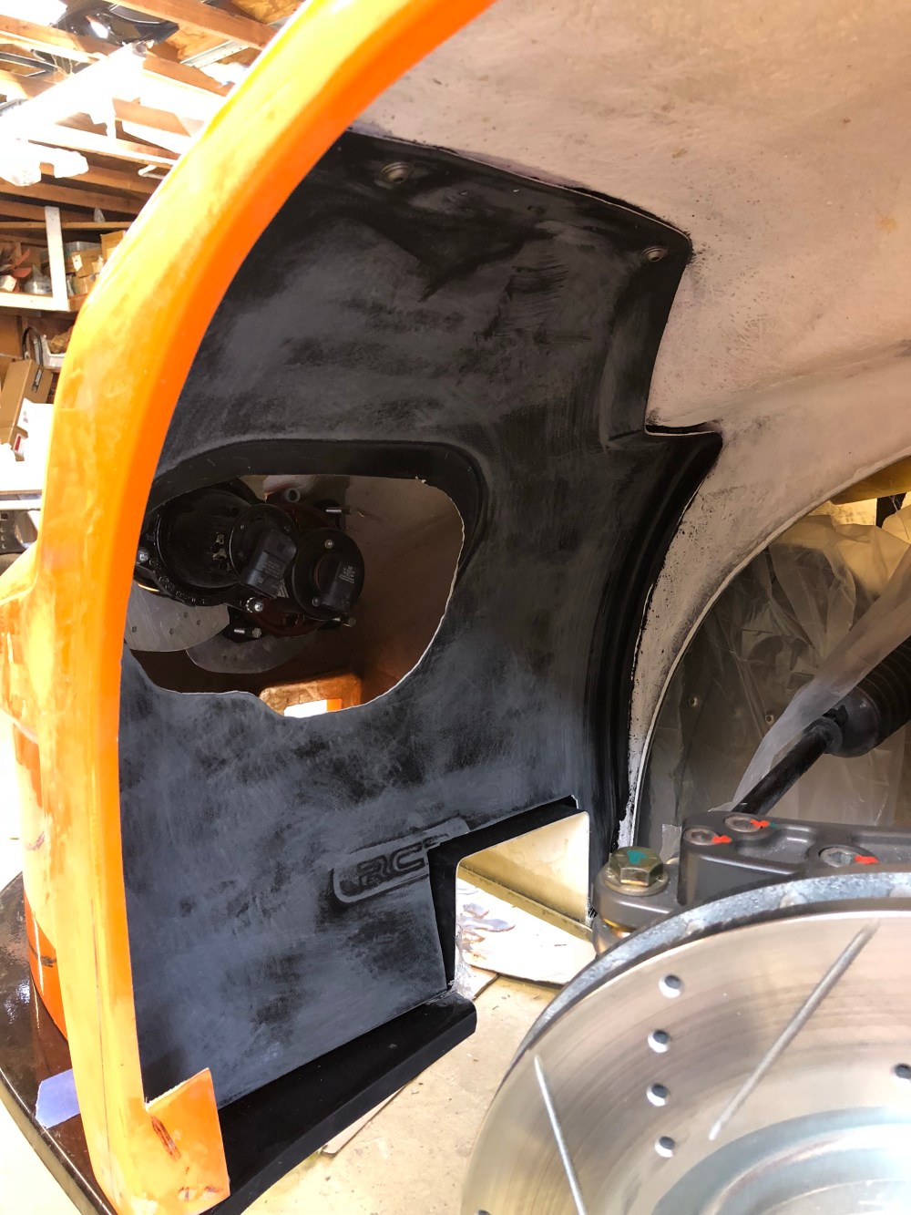
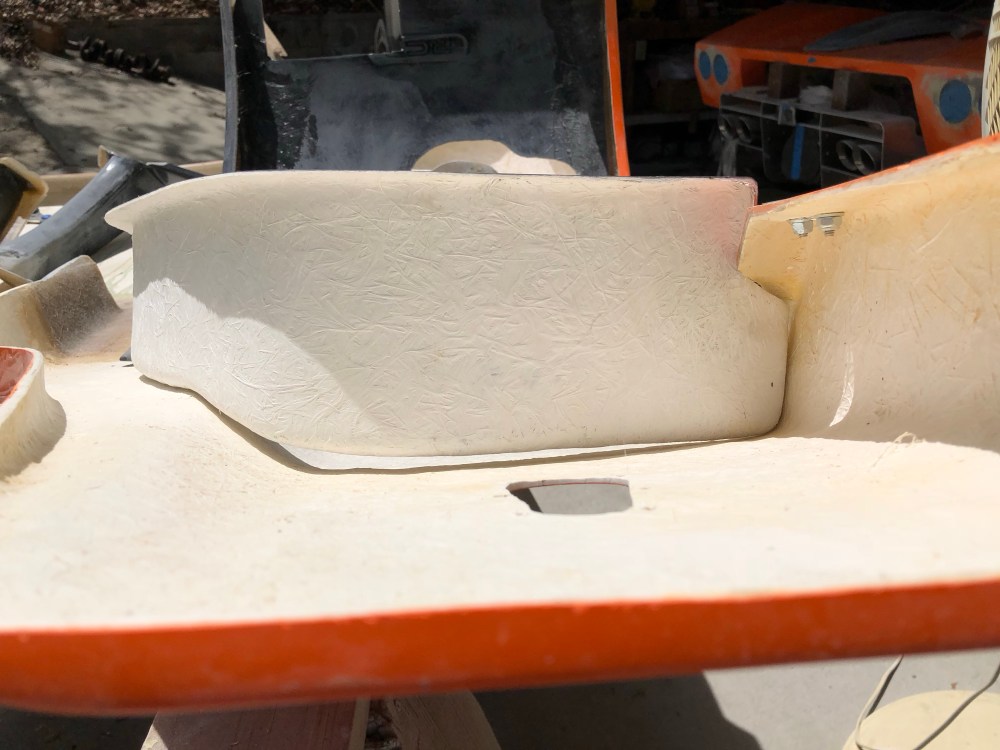
The last piece of the front wheel liner puzzle are 2 J-shaped pieces used to block debris from getting throw toward the interior of the spider. The fit wasn’t too bad – some trimming of the forward edge to mate with the front liner and massaging of the rear should be about all that’s needed.

I’ll attach these last pieces of the front liner once I get my aerocatches installed so I can preload the body and get everything aligned as it should be – I suspect once these pieces are bonded into place the body won’t flex very much.


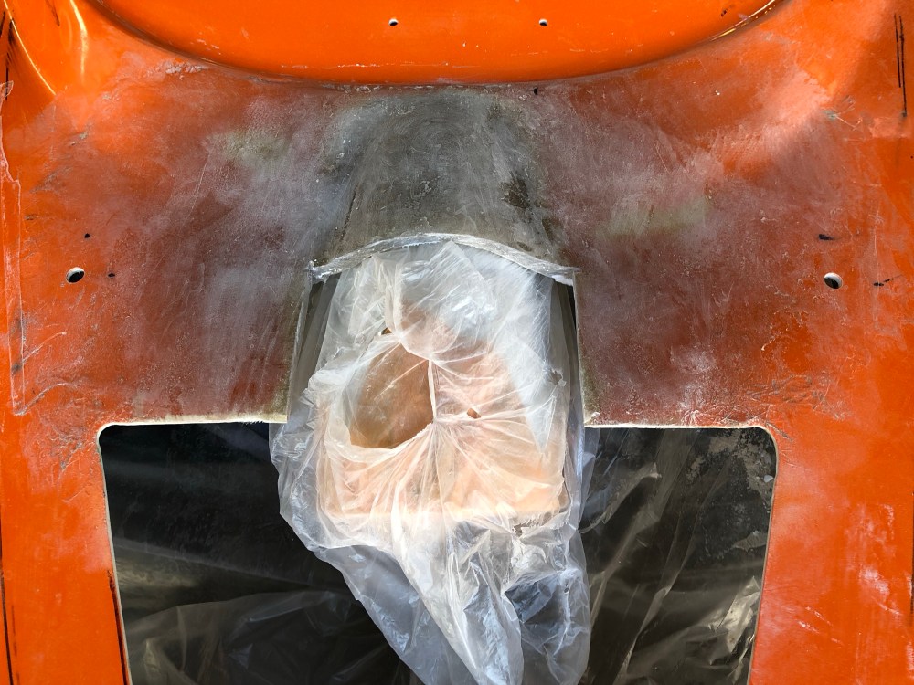
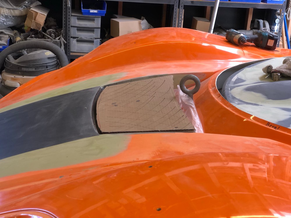
While on the topic of things I would have done differently and hindsight being what it is, I guess it’s inevitable I’d have to go back and fix some of my earlier mistakes. The very first fiberglass modification I did was to add a reinforcement patch where the engine’s intake tube protrudes through the rear clam.


When I glassed this in initially I didn’t add anything between the fiberglass and intake tube to create a gap between the two. This meant the new fiberglass I added would rest against my intake tube at all times – it’s going to vibrate and rub the tube and eventually make it look pretty ugly. What I should have done was to add a small piece of cardboard, THEN fiberglass the reinforcement. The cardboard would provide a small gap between the rear clam and intake tube.


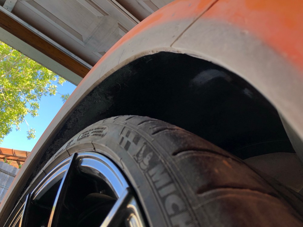
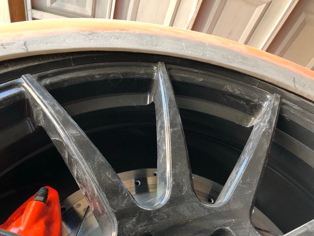
Another item that needed a Go-Back was the recontouring I did of the rear wheel wells. The initial recontouring just didn’t look good – it looked super amateurish. So I threw the towel in and redid the entire wheel well (just about). The new look is much nicer, but it’s at higher risk for tire rubs during suspension compression. To test for rubs I removed the springs from my rear shocks and articulated the suspension until the shocks were fully bottomed. To replicate this condition on the street would mean something went terribly wrong and I broke some stuff.
The good news is – the tire will travel throughout the entire suspension range and can rotate by hand at all positions. The bad news is it’s close. Really close. In reality I think the motions of a wheel rotating at speed and a suspension and rear bodywork vibrating/moving will mean tire rubs are inevitable. It’s difficult to determine how severe those rubs will be. For now, I’ll leave it as it is but a v3.0 of the wheel well may be in the cards. I really didn’t want to add fender flares but it’s the only way I’ll be able to get more clearance for the tire.

OK – enough about things I messed up. One of the pieces I’m most happy with is the air duct I made for the radiator discharge. I haven’t quite figured out how I want the exit to look but know I didn’t like where I had left things. Using some more poster board I made a simple set of “walls” to shape an exit for the duct.
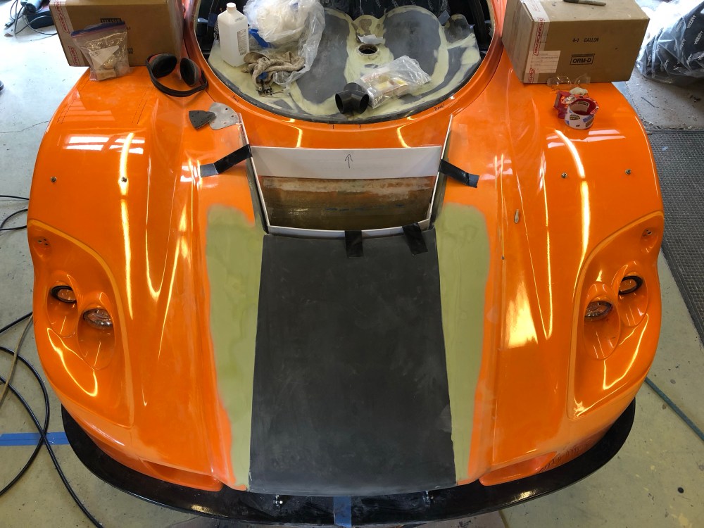
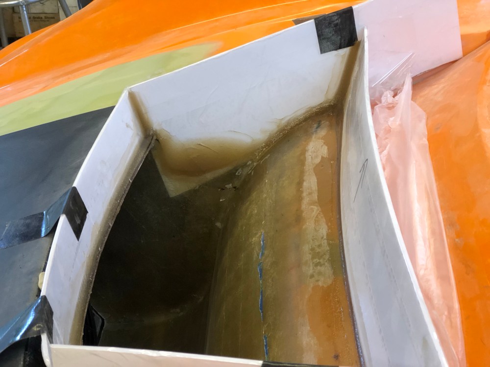
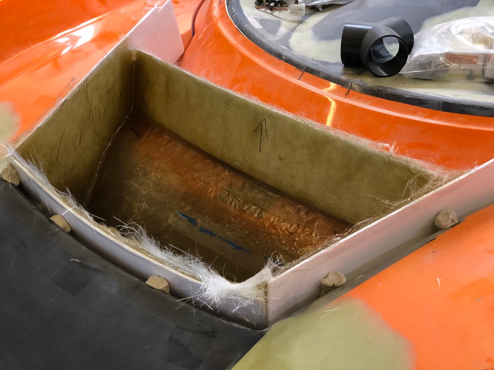

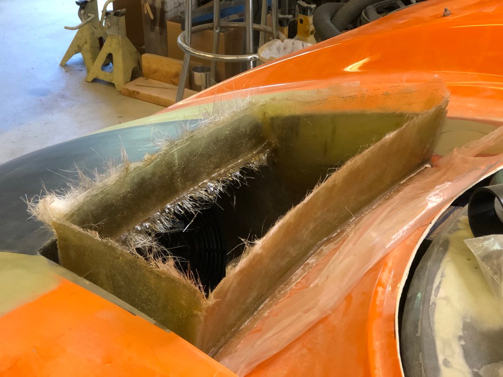
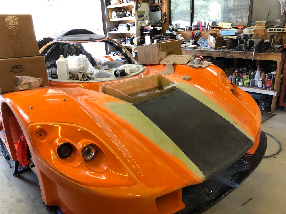


Dumping radiator air just in front of the center of the windshield is about the worst place to do so. The center of the windshield is a high pressure zone – which makes pushing hot air out of the radiator more difficult. I plan to fabricate a small Gurney flap which I’ll be attaching to the rear edge of the hood (where the carbon piece turns down). I’m hoping the Gurney flap will cause enough disturbance/mixing to lessen the high pressure zone immediately in front of the windshield, making it easier for the radiator air to flow out.
After a spell of feeling like I was aimlessly spinning my wheels I’m starting to feel like I’m making tracks again. Getting the splitter laid out and completed and bonding in the front wheel well liners was a real step forward in closing out the work for the front end. Neither the front nor rear liners are complete yet but I need to be careful with the last bits as they’ll really lock the clam geometries and stiffen them. I need to get the aerocatches installed so I can get the preload right before bonding in the last pieces of wheel well liner or I might be fighting more twisted bodywork later.
