Bob has said this multiple times and I’ve experienced it quite a few times – sometimes it seems you’ll spend 2 hours thinking about something that takes less than an hour to complete. If you’ve made it this far you can tell I spend a good portion of the day just sitting on my butt thinking about what to do next, and how to do it as best as possible. I’m constantly making design trades in my head and debating the merits of about 1000 different solutions before I get going on a solution I think is “right”. Even then sometimes it’ll take a question or discussion with someone else to make me rethink that decision I spent so much time laboring over! So it’s no surprise I had the same experience with the brakes. I really struggled to come up with the optimum configuration for the braking system, in particular the e-brake calipers and hydraulic flex hoses.
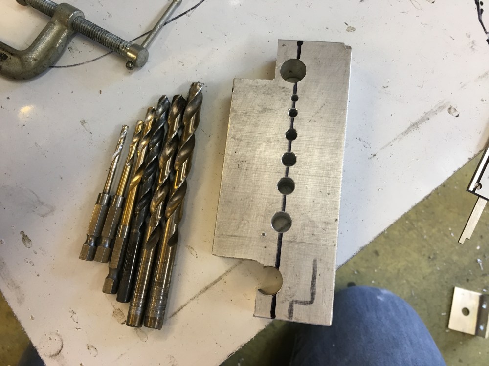
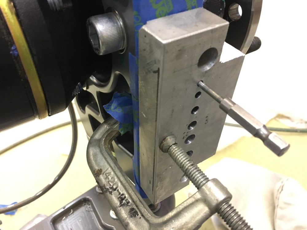
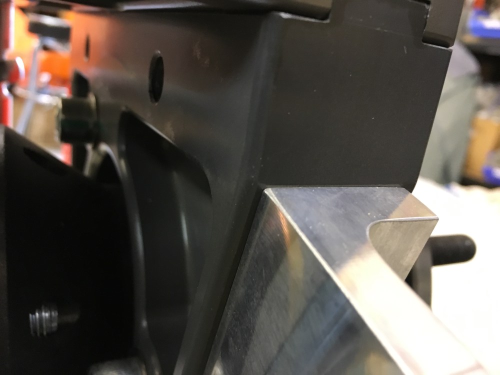
I screwed up early on after having my uprights anodized as I should have machined the necessary mounting holes for the e-brake brackets either before or after anodizing. Now that the suspension’s been assembled and dialed in, taking it all back apart just to tap 2 mounting holes made me feel like a furious beating with a wooden stick would have been more enjoyable. So I’ve been pushing off on tapping these holes for as long as possible since I’d only get 1 shot to do it correctly. Getting the hole spacing wrong or drilling the holes off at whacky angles would assuredly ruin the upright (or so I told myself). I couldn’t put it off any longer so I tried to be as careful as I could with each step. To ensure I drilled the pilot holes perfectly perpendicular to the mounting face I used a piece of scrap aluminum block and drilled holes of increasing size on the drill press. I was sure the drill press would give me nice perpendicular holes which could be used as drill guides once I secured the aluminum block to the upright. I selected a good number of drills to “walk the hole up” to the final size needed for tapping. Minimizing the amount of material removed between each hole size helps to keep the hole clean and ensures the bit won’t grab or twist instead of cutting.
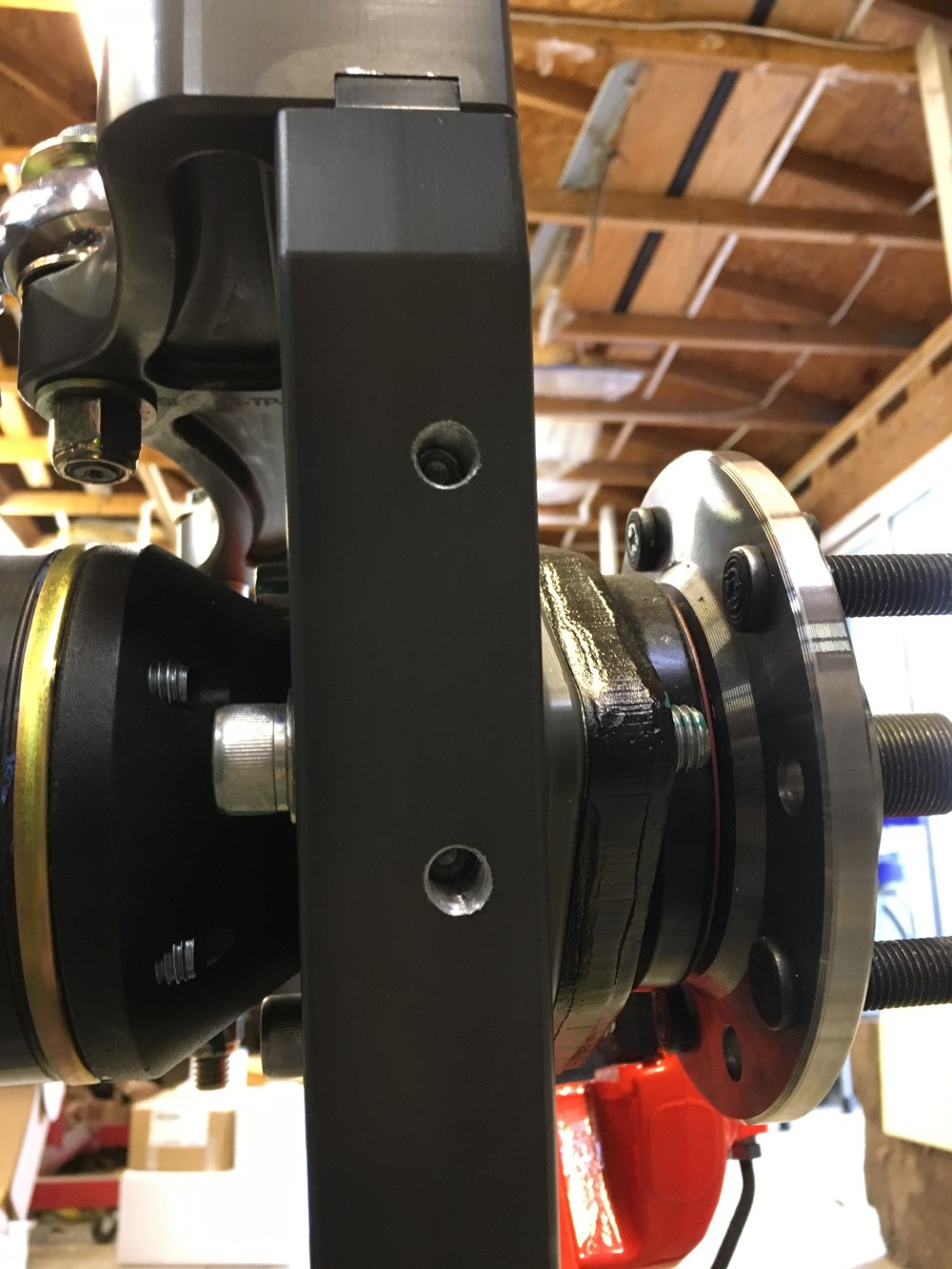
I decided I would use M10x1.5 bolts for the mounting hardware. The upright is pocketed on both the inboard and outboard faces; based on my rough measurements the inboard side is pocketed to a depth of 17mm, the outboard to a depth of 6mm, with the upright having an overall thickness of 39mm (I probably got this measurement wrong and the actual thickness is 40mm). This meant the centerline of my mounting bracket needed to be 8mm away from the outboard edge. Putting the tapped holes at 19.5mm (or centered) would have resulted in the threaded hole getting exposed once it hit the pocketed portion of the upright.
For vertical alignment, I aligned the upper edge of the mounting bracket to the corner where the upright turns from angled to vertical. This places the caliper square to the spindle centerline so the curve of the rotor hat and wheel match the curve in the e-brake caliper. Get this position wrong and it’ll look like the caliper is twisted relative to the rotor – bleh.
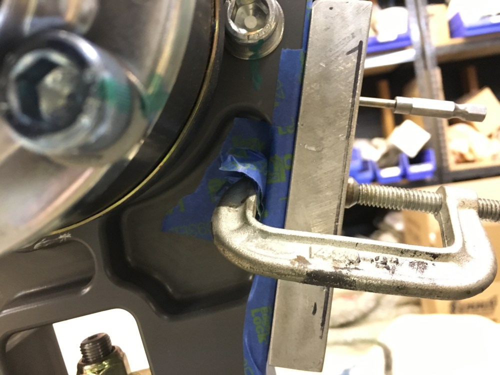
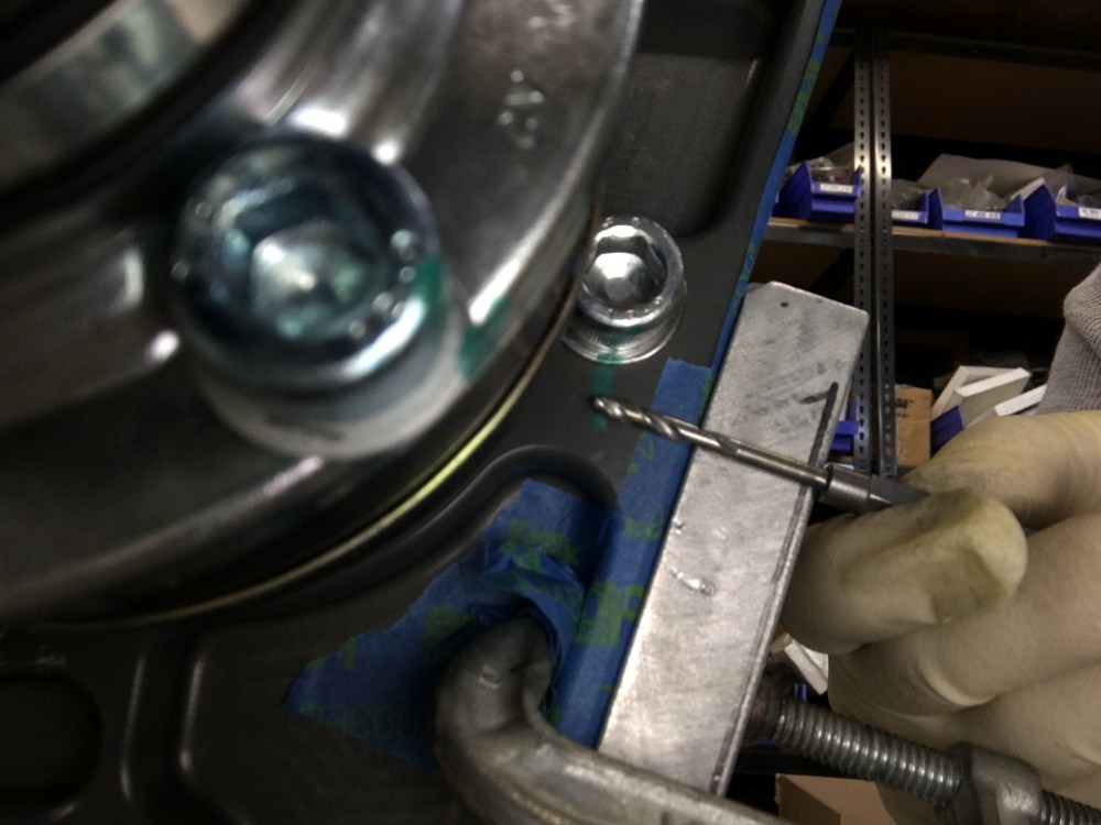
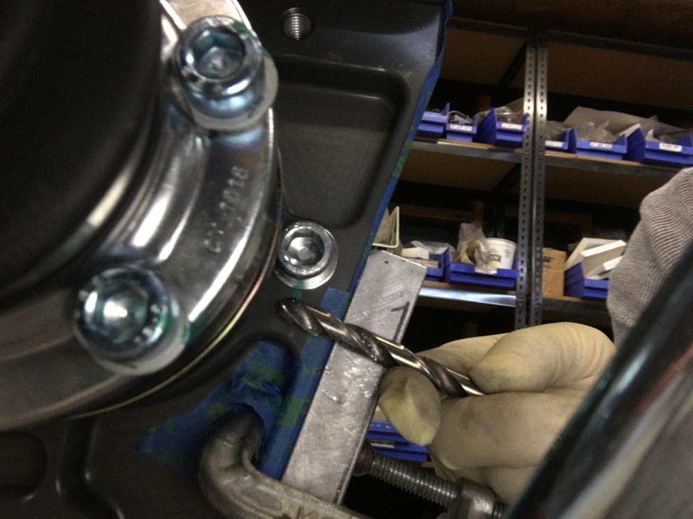
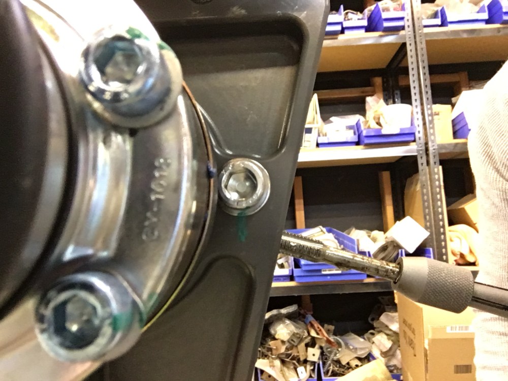
I used a small c-clamp to secure my drilling fixture to the upright after marking my first hole – time to start drilling!
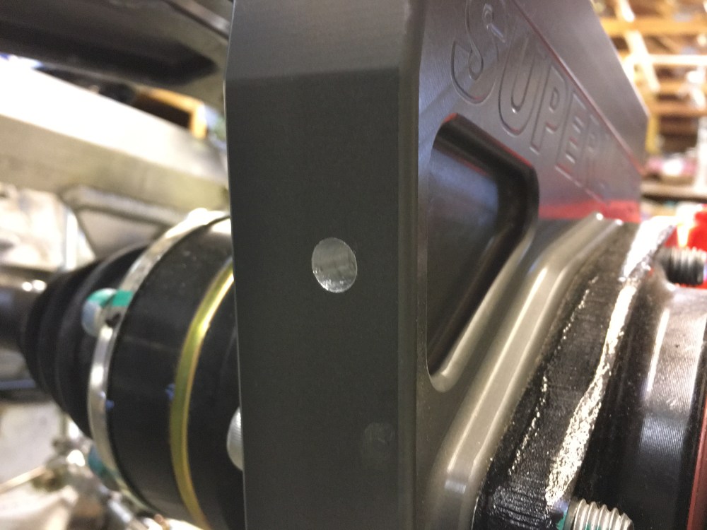
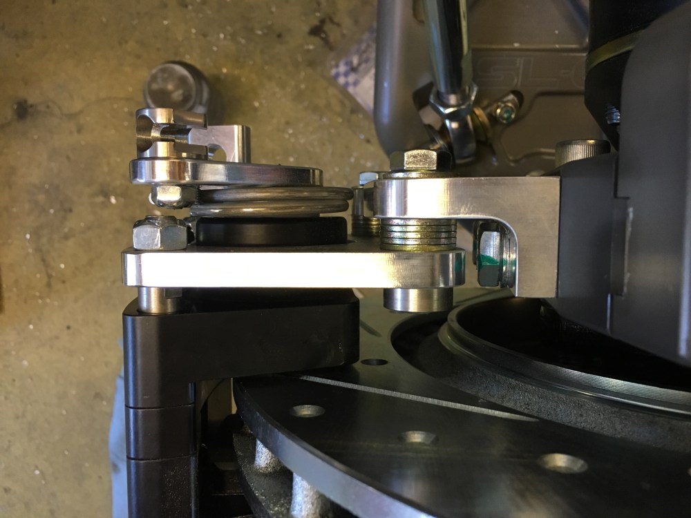
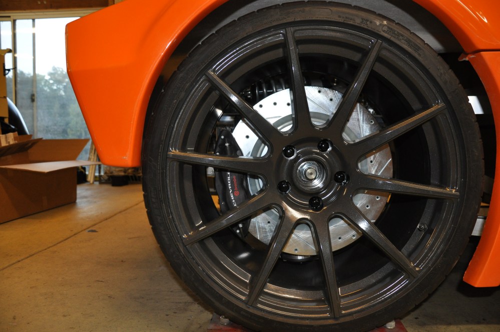
The e-brake calipers supplied in the kit are really nice units. They’re finished in a really nice black anodize and the mounting brackets are billet. I found it odd, but only one of my calipers came with the letters “SL-C” on the exterior face – the other side was blank. I’m toying with the idea of powdercoating these eventually but my experience with the calipers leads me to believe I won’t be able to create a close enough match of the orange – so I’d have 2 different shades of orange fairly close to each other which might push my OCD issues into overdrive. Best to just leave it as-is methinks.

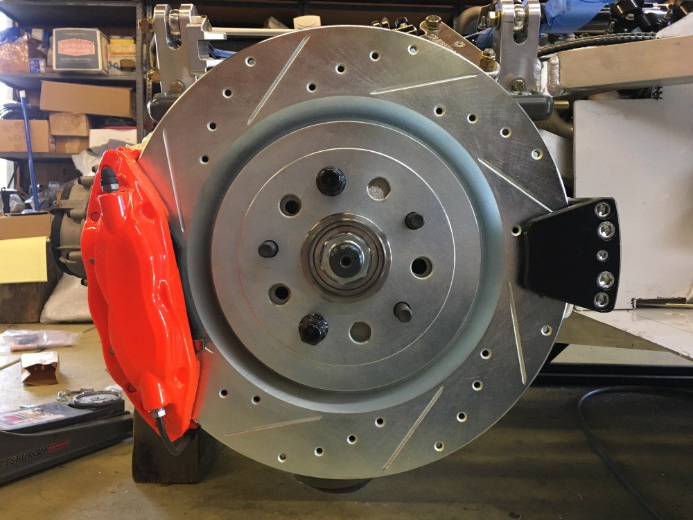
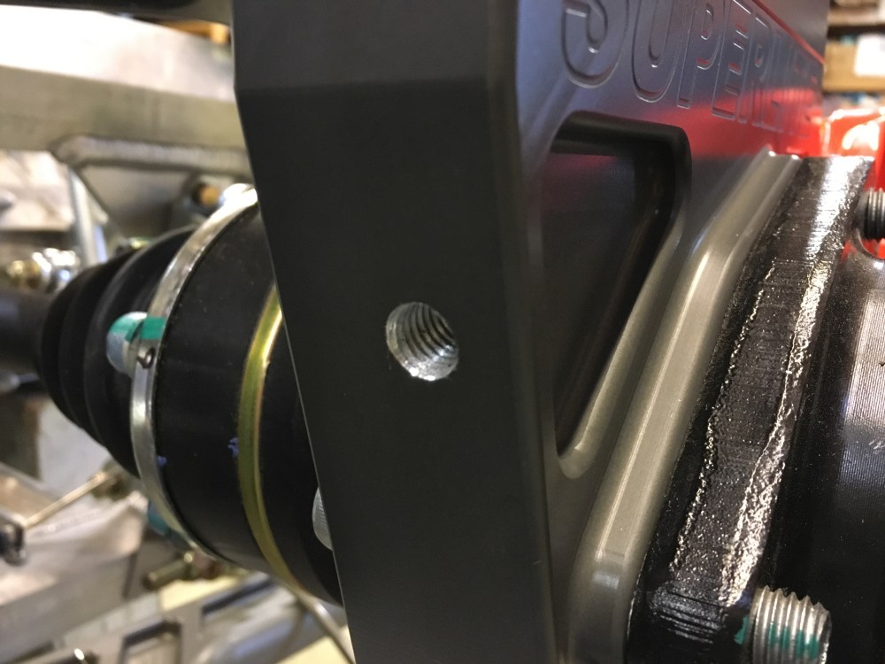
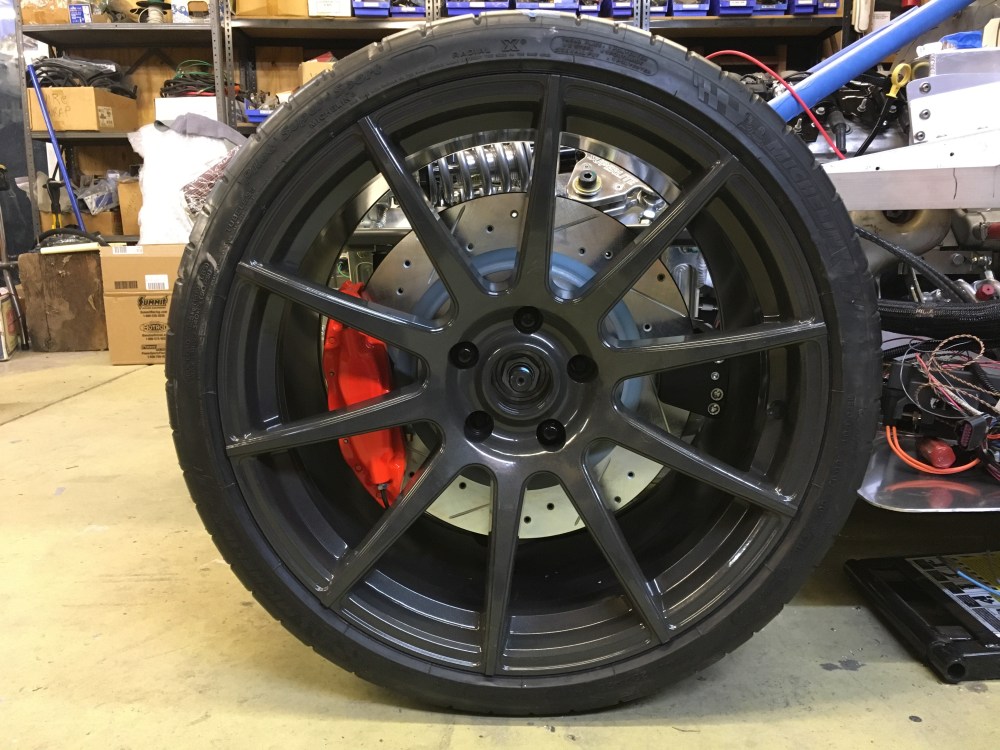
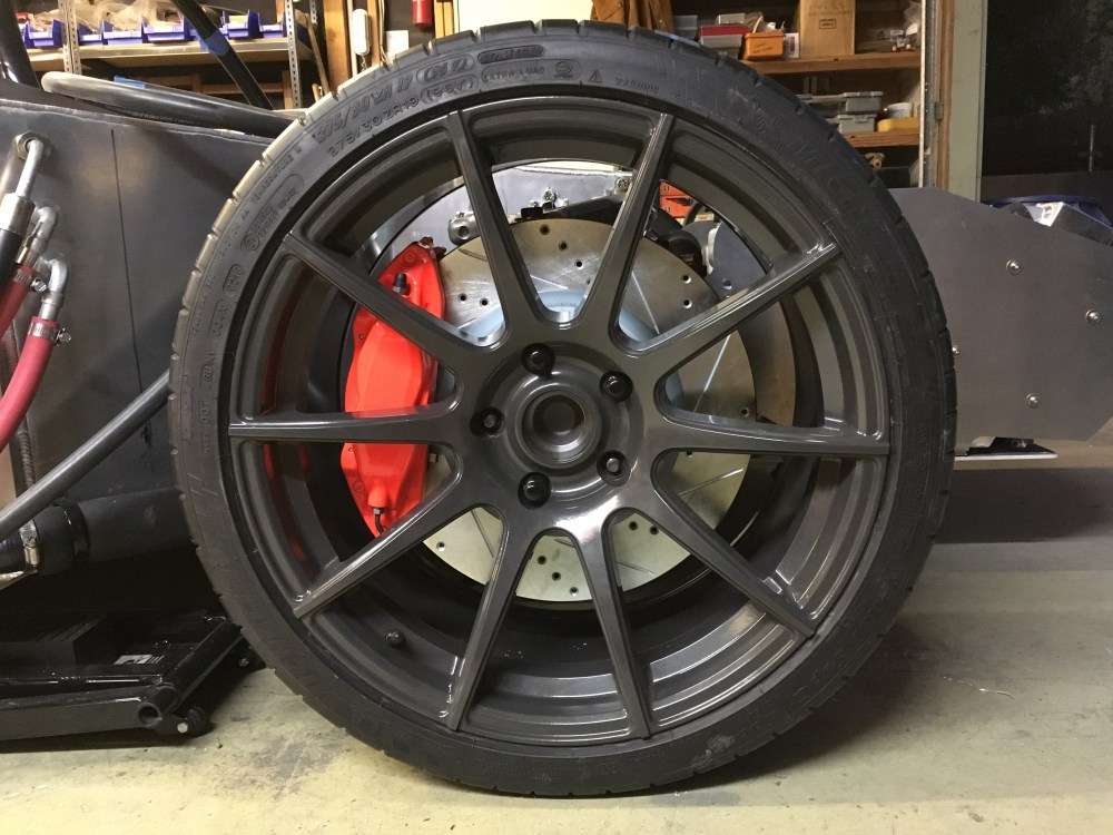
Surprisingly, the procedure went smoothly and I mounted the e-brake calipers without any drama. Before vs after pic; I always get jazzed seeing how well the calipers turned out and in combination with the CF10 wheels.

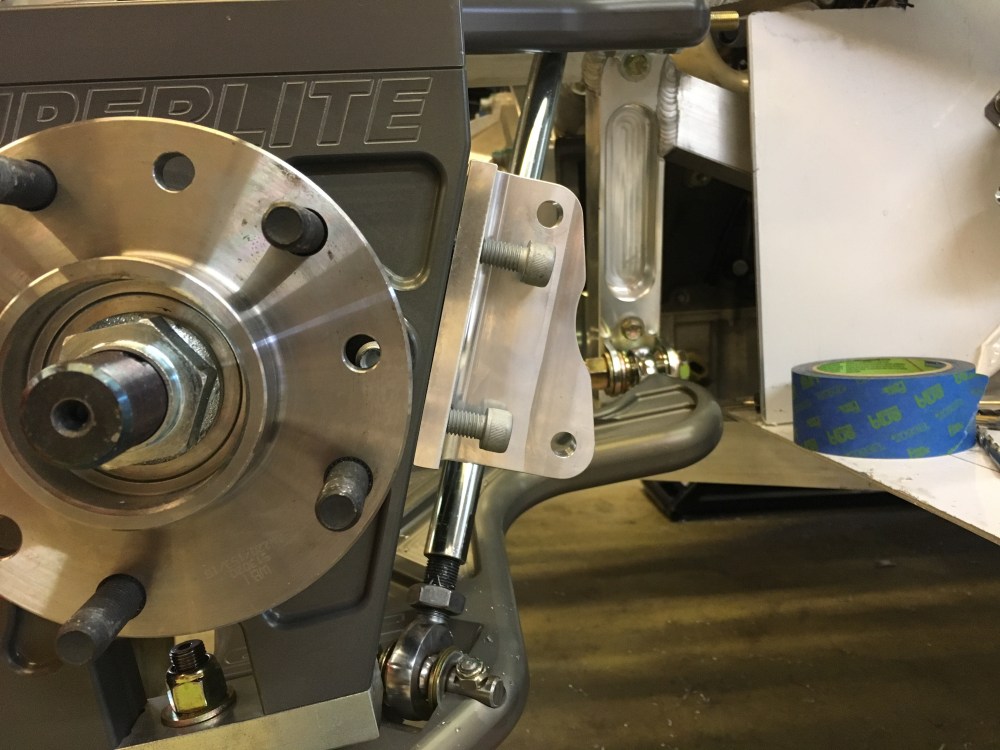
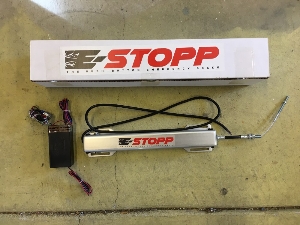
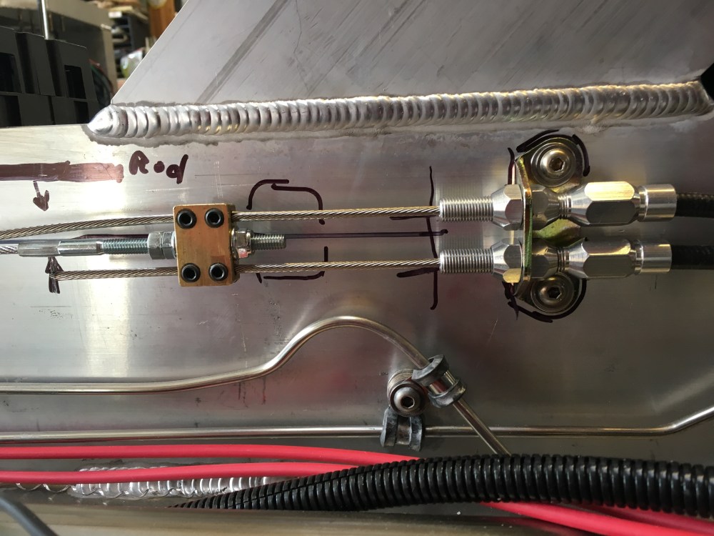
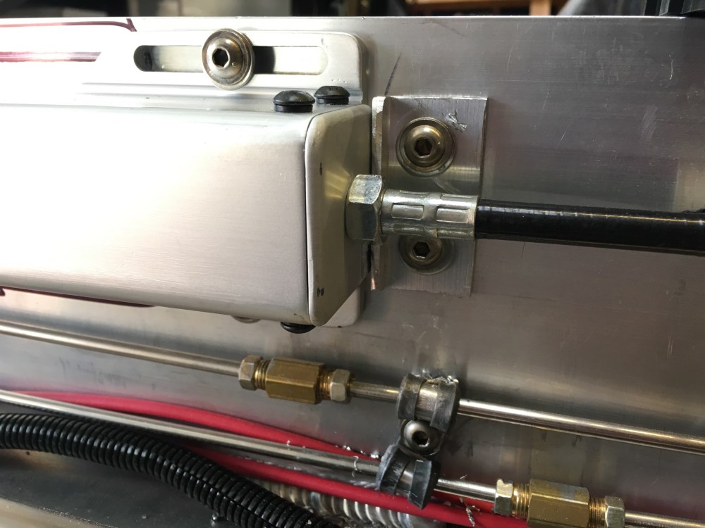
Next up was install of the E-stopp emergency brake system. I think “emergency brake” is a bit of a misnomer since the system has a disable switch that prevents it from working while the ignition is on. It’s really just an electronic parking brake – which is what I wanted, no plans for handbrake turns for me! Installation was pretty straightforward. About the only thing I’d recommend is powering up the system and actuating it before performing final installation to ensure it’s in the fully extended position while tightening down on the e-brake pull cables. If the actuator is in a mid-position then there may not be sufficient cable actuation during operation. I had read in an online review of the system that this occurred to one user and they had to tear into their system to readjust the cable setpoints. Since I opted to bury this behind the spider, accessing this after the car is complete would be major work.
Brake lines:
As with the e-brake calipers, I was putting off on completing the flex line install for the brembos. The hoses and banjo fittings supplied in the kit just didn’t work well – I think these are likely hoses and fittings designed back when the hard lines used to be run inside the footbox. Now that they’re run on the outside of the footbox they didn’t seem to work very well. Some of the issues/concerns I was encountering:
- The front brake calipers do not have an integrally cast anti-rotation ear.
- The flex lines are too short to run in a way that a strain relief can be added.
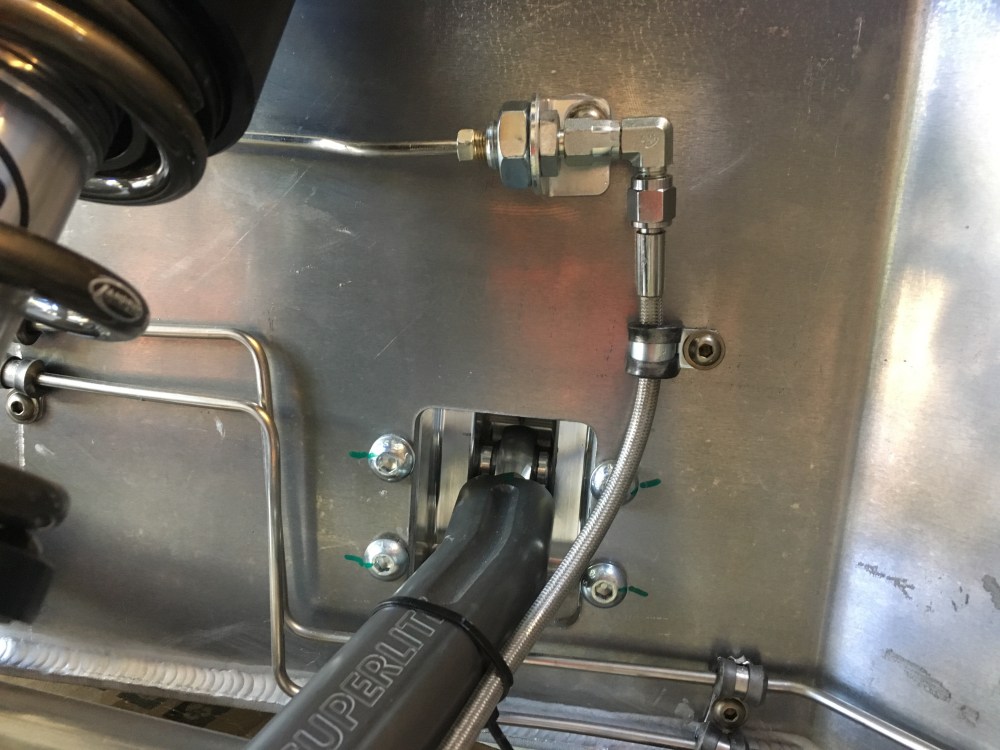
- The flex lines need to make a quick turn before hitting the 45-deg angled portion of the foot box.
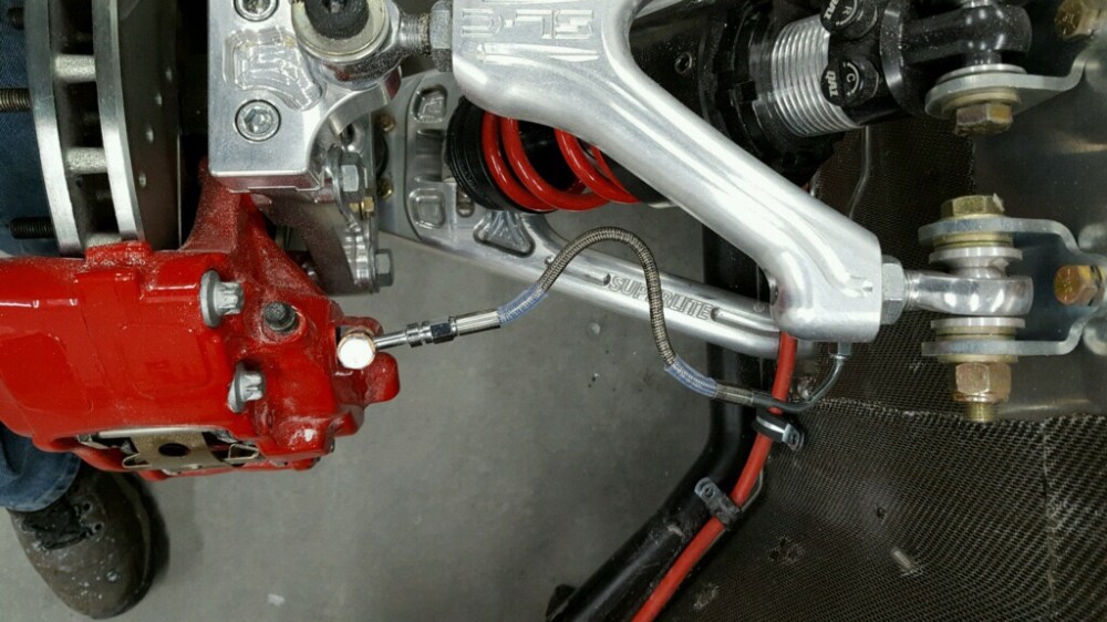
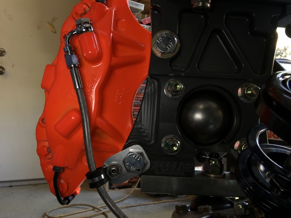
To rectify the first two issues I procured a longer off-the-shelf hose from a local hose vendor. 24″ was the closest size they had which would work for me. YMMV so measure if you decide to replace your hoses. The longer flex line gave me enough slack to install anti-rotation strain relief tabs using a caliper mounting bolt to hold it in place. There was also enough length so I could zip-tie the hose to the rearward arm of the lower a-arm. The new assembly has slack for the suspension to fully articulate in the vertical direction with the wheel turning full lock to lock. Low tech – yes, but the zip-ties are effective at keeping the flex line away from the wheel and coil spring.
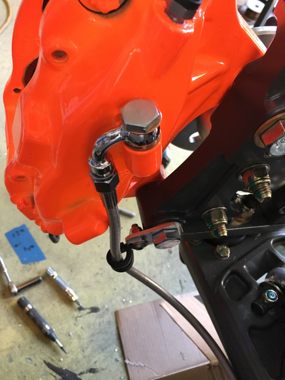
To address the third point I used a 90-deg male/female -3AN adapter to turn the hose downward at the hard line joint. It would have been better to have a 90-deg end fitted to the hose but I didn’t want to pay extra or spend the time for a custom line. I also purchased a 90-deg banjo fitting to orient the hose downward off the caliper attachment point.

In the rear, I used the kit-supplied flex line that has the integral 90-deg hose end along with a straight banjo fitting. I still need to make some anti-rotation brackets similar to what I did for the fronts. The rear flex lines were less of an issue because they don’t need to accommodate for a wheel which is steered.
